DTC B2278 Engine Switch Circuit Malfunction |
| DTC Code | Detection Condition | Trouble Area |
| B2278 | Communication is abnormal between main body ECU and engine switch or engine switch is defective |
|
| 1.READ VALUE OF INTELLIGENT TESTER (START SWITCH 1 AND 2) |
Use the Data List to check if the engine switch is functioning properly.
| Tester Display | Measurement Item/Range | Normal Condition | Diagnostic Note |
| Start Switch 1 | Start Switch 1/ON or OFF | ON: Engine switch on (IG) OFF: Engine switch off | - |
| Start Switch 2 | Start Switch 2/ON or OFF | ON: Engine switch on (IG) OFF: Engine switch off | - |
|
| ||||
| OK | |
| 2.CHECK ENGINE SWITCH (SWITCH CONDITION) |
Ensure the key is inside the cabin.
Check that the power source mode changes as shown below each time the engine switch is pushed.
|
| ||||
| OK | ||
| ||
| 3.INSPECT ENGINE SWITCH |
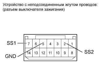 |
Remove the engine switch.
Measure the resistance according to the value(s) in the table below.
| Tester Connection | Switch Condition | Specified Condition |
| 7 (SS1) - 5 (GND) | Pushed | Below 1 Ω |
| 2 (SS2) - 5 (GND) | Pushed | Below 1 Ω |
| 7 (SS1) - 5 (GND) | Not pushed | 10 kΩ or higher |
| 2 (SS2) - 5 (GND) | Not pushed | 10 kΩ or higher |
|
| ||||
| OK | |
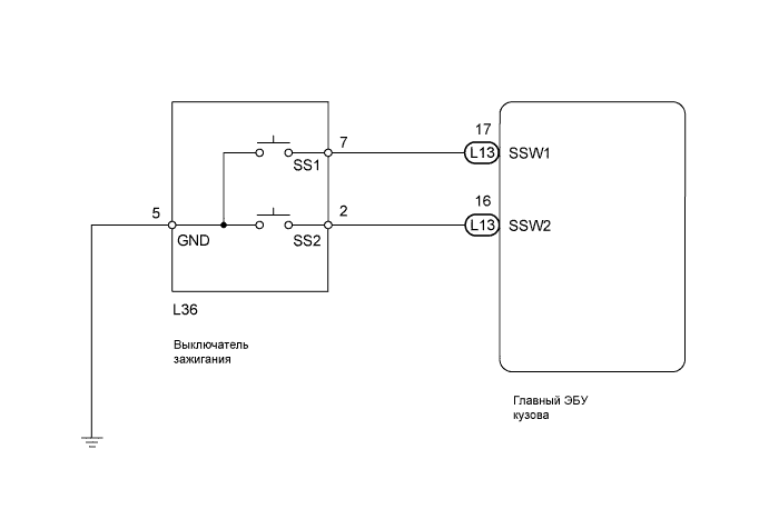
| 4.CHECK HARNESS AND CONNECTOR (ENGINE SWITCH - MAIN BODY ECU AND BODY GROUND) |
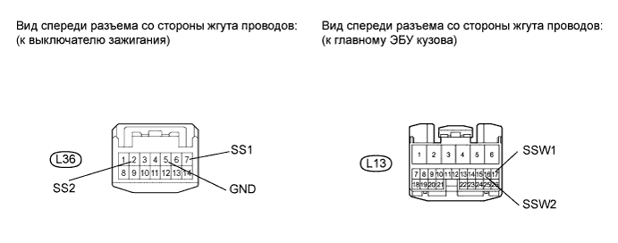
Disconnect the L36 engine switch connector.
Disconnect the L13 main body ECU connector.
Measure the resistance according to the value(s) in the table below.
| Tester Connection | Condition | Specified Condition |
| L36-7 (SS1) - L13-17 (SSW1) | Always | Below 1 Ω |
| L36-2 (SS2) - L13-16 (SSW2) | Always | Below 1 Ω |
| L36-5 (GND) - Body ground | Always | Below 1 Ω |
| L36-7 (SS1) or L13-17 (SSW1) - Body ground | Always | 10 kΩ or higher |
| L36-2 (SS2) or L13-16 (SSW2) - Body ground | Always | 10 kΩ or higher |
|
| ||||
| OK | ||
| ||
