СИСТЕМА ПОСАДКИ И ЗАПУСКА > Двигатель не запускается |
| ENGINE START SYSTEM OPERATION |
When the engine switch is pressed with the brake pedal depressed and shift lever in P or N, the main body ECU determines that it is an engine start request.
The certification ECU and other ECUs perform key verification via the LIN communication line. The engine switch indicator light illuminates in green.
The main body ECU activates the D-ACC, D-IG1 and IG2 relays.
The certification ECU outputs a steering UNLOCK signal. The signal is sent to the steering lock ECU via the LIN communication line.
The main body ECU sends an engine start request signal to the ECM.
The ECM sends an ACC cut request signal to the main body ECU.
The ECM and main body ECU activate the ST cut relay.
The main body ECU deactivates the D-ACC relay until the ECU detects an engine start.
The ECU reactivates the D-ACC relay and turns off the engine switch indicator light.
| Symbols of main body ECU | Signals |
| SSW1/SSW2 | Engine switch on (ACC, IG) signal |
| ACCD | D-ACC relay operation signal |
| IG2D | IG2 relay operation signal |
| STR2 | ST CUT relay operation signal |
| STR | Park / neutral position switch signal |
| STP | Stop light switch signal |
| TACH | Engine start detection signal |
| STSW | Starter activation request signal |
| ACCR | ACC cut request signal |

| 1.CHECK WHETHER ENGINE STARTS AFTER STEERING LOCK INITIALIZATION |
Open and close the driver door when the engine switch is off.
Check that the engine starts.
|
| ||||
| NG | |
| 2.CHECK WHETHER DTC OUTPUT RECURS (MAIN BODY ECU AND CERTIFICATION ECU) |
Clear the DTCs.
Check for DTCs again.
|
| ||||
| OK | |
| 3.CHECK ENGINE SWITCH (SWITCH CONDITION) |
Ensure the key is inside the cabin.
With the brake pedal released, check that the power source mode changes as shown below each time the engine switch is pushed.
|
| ||||
| OK | |
| 4.CHECK BASIC FUNCTION |
Ensure that there is fuel in the fuel tank and the key is inside the cabin.
Depress the brake pedal with the shift lever in P or N, and keep depressing the pedal.
Check that the engine cranks when the engine switch is pressed.
|
| ||||
| NG | |
| 5.READ VALUE OF INTELLIGENT TESTER (PARK / NEUTRAL POSITION SWITCH) |
Use the Data List to check if the park / neutral position switch is functioning properly.
| Tester Display | Measurement Item/Range | Normal Condition | Diagnostic Note |
| Neutral SW / Clutch SW | Park / neutral position switch/ON or OFF | ON: Shift lever in P or N OFF: Shift lever in R or D | - |
|
| ||||
| OK | |
| 6.READ VALUE OF INTELLIGENT TESTER (STOP LIGHT SWITCH) |
Use the Data List to check if the stop light switch is functioning properly.
| Tester Display | Measurement Item/Range | Normal Condition | Diagnostic Note |
| Stop Light SW | Stop Light switch/ON or OFF | ON: Brake pedal is depressed OFF: Brake pedal is released | - |
|
| ||||
| OK | |
| 7.CHECK STEERING LOCK SYSTEM |
When the engine switch is on (ACC), check that the steering lock can be released.
|
| ||||
| OK | |
| 8.INSPECT MAIN BODY ECU |
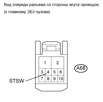 |
Disconnect the A68 main body ECU connector.
Depress the brake pedal with the shift lever in P or N, and keep depressing the pedal.
Measure the voltage according to the value(s) in the table below.
| Tester Connection | Condition | Specified Condition |
| A68-4 (STSW) - Body ground | When the engine cranks by pressing the engine switch. | 11 to 14 V |
|
| ||||
| OK | ||
| ||
| 9.READ VALUE OF INTELLIGENT TESTER (ENGINE START REQUEST) |
Use the Data List to check if the engine start request is functioning properly.
| Tester Display | Measurement Item/Range | Normal Condition | Diagnostic Note |
| Engine Start Request | Starter request signal/Yes or No | YES: ID code box receives immobiliser unset signal NO: ID code box does not receive immobiliser unset signal | - |
|
| ||||
| OK | ||
| ||
