DTC P0031 Oxygen Sensor Heater Control Circuit Low (Bank 1 Sensor 1) |
DTC P0032 Oxygen Sensor Heater Control Circuit High (Bank 1 Sensor 1) |
DTC P0051 Oxygen Sensor Heater Control Circuit Low (Bank 2 Sensor 1) |
DTC P0052 Oxygen Sensor Heater Control Circuit High (Bank 2 Sensor 1) |
DTC P0135 Oxygen (A/F) Sensor Heater Circuit (Bank 1 Sensor 1) |
DTC P0155 Oxygen (A/F) Sensor Heater Circuit Malfunction (Bank 2 Sensor 1) |
| DTC No. | DTC Detection Condition | Trouble Area |
| P0031 P0051 | Heated oxygen sensor heater current is below 0.3 A when heater operates with +B greater than 11.5 V (1 trip detection logic) |
|
| P0032 P0052 | Heater current exceeds 2 A when heater operates (1 trip detection logic) |
|
| P0135 P0155 | Cumulative heater resistance correction value exceeds threshold (2 trip detection logic) |
|
| 1.INSPECT HEATED OXYGEN SENSOR (HEATER RESISTANCE) |
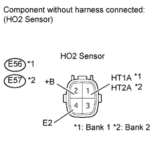 |
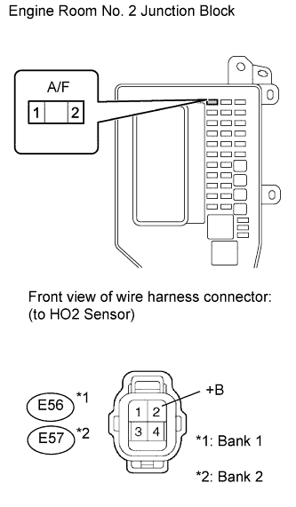
Disconnect the E56 and E57 sensor connectors.
Measure the resistance according to the value(s) in the table below.
| Tester Connection | Condition | Specified Condition |
| 1 (HT1A) - 2 (+B) | Always | 5 to 10 Ω |
| 1 (HT2A) - 2 (+B) | Always | 5 to 10 Ω |
| 1 (HT1A) - 4 (E2) | Always | 10 kΩ or higher |
| 1 (HT2A) - 4 (E2) | Always | 10 kΩ or higher |
|
| ||||
| OK | |
| 2.CHECK HARNESS AND CONNECTOR (HEATER POWER SOURCE) |
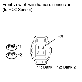 |
Disconnect the E56 or E57 sensor connector.
Turn the engine switch on (IG).
Measure the voltage according to the value(s) in the table below.
| Terminal Connections | Switch Condition | Specified Condition |
| E56-2 - Body ground | Engine switch on (IG) | 11 to 14 V |
| E57-2 - Body ground | Engine switch on (IG) | 11 to 14 V |
|
| ||||
| OK | |
| 3.CHECK HARNESS AND CONNECTOR (ECM - HEATED OXYGEN SENSOR AND BODY GROUND) |
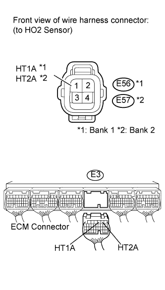  |
Disconnect the E56 and E57 sensor connectors.
Disconnect the E3 ECM connector.
Measure the resistance of the fuse.
| Tester Connection | Condition | Specified Condition |
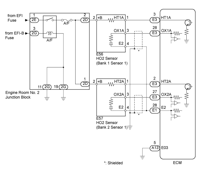
| E56-1 (HT1A) - E3-3 (HT1A) | Always | Below 1 Ω |
| E57-1 (HT2A) - E3-2 (HT2A) | Always | Below 1 Ω |
| E56-1 (HT1A) or E3-3 (HT1A) - Body ground | Always | 10 kΩ or higher |
| E57-1 (HT2A) or E3-2 (HT2A) - Body ground | Always | 10 kΩ or higher |
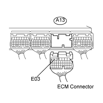
Disconnect the A13 ECM connector.
Measure the resistance according to the value(s) in the table below.
| Tester Connection | Condition | Specified Condition |
| A13-5 (E03) - Body ground | Always | 10 kΩ or higher |
|
| ||||
| OK | ||
| ||
| 4.INSPECT A/F FUSE |
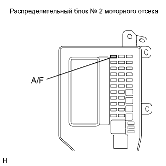 |
Remove the A/F fuse from the engine room No. 2 junction block.
Measure the resistance of the fuse.
| Tester Connection | Condition | Specified Condition |
| A/F fuse | Always | Below 1 Ω |
|
| ||||
| OK | |
| 5.INSPECT ENGINE ROOM NO. 2 JUNCTION BLOCK (A/F RELAY) |
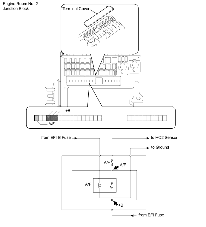
Remove the terminal cover.
Measure the voltage according to the value(s) in the table below.
| Tester Connection | Switch Condition | Specified Condition |
| +B - Body ground | Always | 11 to 14 V |
| A/F - Body ground | Engine switch on (IG) | 11 to 14 V |
|
| ||||
| OK | |
| 6.CHECK HARNESS AND CONNECTOR (HEATED OXYGEN SENSOR - INTEGRATION RELAY) |
 |
Disconnect the E56 and E57 sensor connectors.
Remove the A/F fuse from the engine room No. 2 junction block.
Measure the resistance according to the value(s) in the table below.
| Tester Connection | Condition | Specified Condition |
| A/F fuse terminal 2 - E56-2 (+B) | Always | Below 1 Ω |
| A/F fuse terminal 2 - E57-2 (+B) | Always | Below 1 Ω |
| A/F fuse terminal 2 or E56-2 (+B) - Body ground | Always | 10 kΩ or higher |
| A/F fuse terminal 2 or E57-2 (+B) - Body ground | Always | 10 kΩ or higher |
|
| ||||
| OK | ||
| ||
