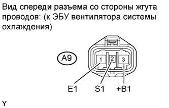
ЭБУ ВЕНТИЛЯТОРА СИСТЕМЫ ОХЛАЖДЕНИЯ > ПРОВЕРКА БЕЗ СНЯТИЯ С АВТОМОБИЛЯ |
| 1. CHECK COOLING FAN ECU |
Remove the front controllers cover.
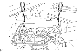 |
Using a screwdriver, detach the 2 claws and disconnect the front controller.
Check the resistance of the wire harness between the front controller B14-22 (FAN1) and cooling fan ECU A9-2 (S1).
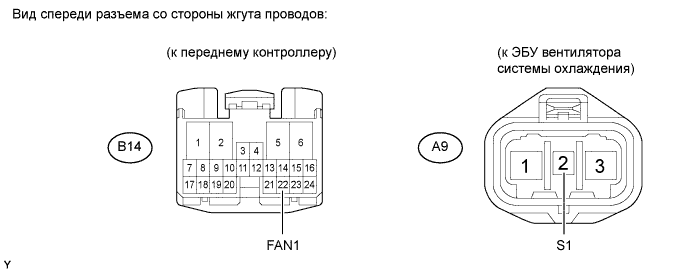
| Tester Connection | Specified Condition |
| B14-22 (FAN1) - A9-2 (S1) | Below 1 Ω |
| B14-22 (FAN1) - Body ground A9-2 (S1) - Body ground | 10 kΩ or higher |
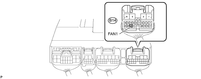
Check the output signal from the front controller.
Set the oscilloscope probe to the terminal B14-22 (FAN1) of the front controller.
Connect the intelligent tester to the DLC3.
Using the intelligent tester, check the waveform.
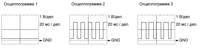
| Condition | Input Signal |
| Engine stopped (engine switch on (IG)) | Waveform 1 (Duty ratio 0%) |
| Engine idling (A/C OFF) | Waveform 1 (Duty ratio 0%) |
| Engine idling (A/C ON) | Waveform 2 (Duty ratio 50 to 70%) |
| Engine idling (engine coolant temperature sensor connector disconnected) | Waveform 3 (Duty ratio 60 to 70%) |
 |
Check the input voltage.
Disconnect the cooling fan ECU connector.
Turn the engine switch on (IG). Check the voltage of the A9-3 (+B1) terminal on the wire harness side.
Connect the cooling fan ECU connector.
Check wire harness (Cooling fan ECU and body ground).
Disconnect the cooling fan ECU connector.
Measure the resistance of the A9-1 (E1) and body ground.
Connect the cooling fan ECU connector.
Check the cooling fan motor (see page Нажмите здесь).
If the result is not as specified, replace the cooling fan motor.
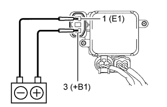 |
Check the cooling fan motor operation.
Disconnect the cooling fan ECU connector.
Connect the battery to the cooling fan ECU at terminals 3 (+B1) and 1 (E1).
Check that the cooling fan motor rotates.
If it does not operate, replace the cooling fan ECU.
