DTC P0365 Camshaft Position Sensor "B" Circuit (Bank 1) |
DTC P0367 Camshaft Position Sensor "B" Circuit Low Input (Bank 1) |
DTC P0368 Camshaft Position Sensor "B" Circuit High Input (Bank 1) |
DTC P0390 Camshaft Position Sensor "B" Circuit (Bank 2) |
DTC P0392 Camshaft Position Sensor "B" Circuit Low Input (Bank 2) |
DTC P0393 Camshaft Position Sensor "B" Circuit High Input (Bank 2) |
| DTC No. | DTC Detection Condition | Trouble Area |
| P0365 P0390 |
|
|
| P0367 P0392 | Output voltage of VVT sensor for exhaust side 0.3 V or less for 4 seconds (1 trip detection logic) |
|
| P0368 P0393 | Output voltage of VVT sensor for exhaust side 4.7 V or more for 4 seconds (1 trip detection logic) |
|
| Item | Content |
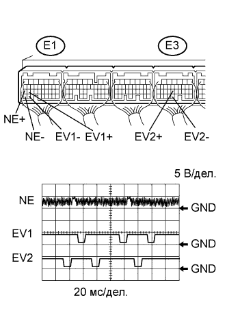
| Terminal | NE+ - NE- EV1+ - EV1- EV2+ - EV2- |
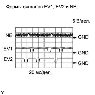
| Equipment Setting | 5 V/DIV., 20 msec./DIV. |
| Condition | Cranking or idling |
| 1.CHECK ECM TERMINAL VOLTAGE |
 |
Inspect the ECM using an oscilloscope.
While the engine is idling, check the waveform between the terminals of the ECM connector.
| Tester Connection | Condition | Specified Condition |
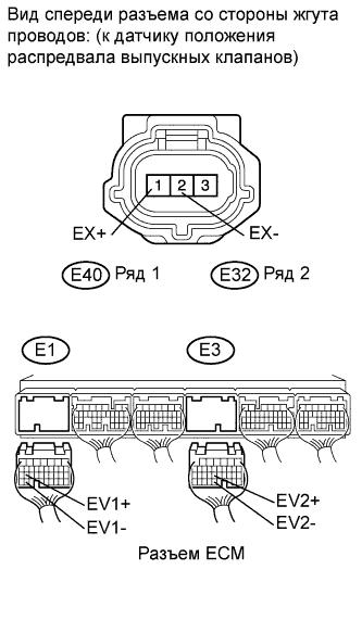
| E1-26 (EV1+) - E1-33 (EV1-) | Engine idling | Correct waveform appears as shown |
| E3-22 (EV2+) - E3-29 (EV2-) | Engine idling | |
| E1-27 (NE+) - E1-34 (NE-) | Engine idling |
|
| ||||
| NG | |
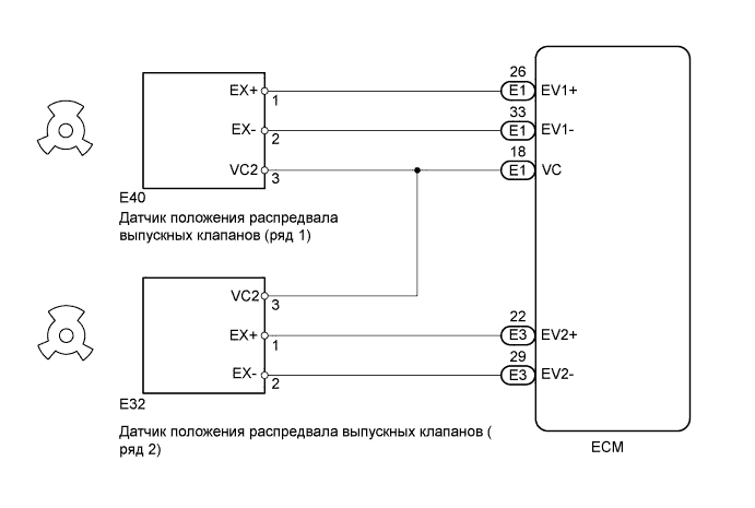
| 2.CHECK VVT SENSOR (SENSOR POWER SOURCE) |
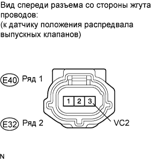 |
Disconnect the E32 or E40 VVT sensor connector.
Turn the engine switch on (IG).
Measure the voltage according to the value(s) in the table below.
| Tester Connection | Switch Condition | Specified Condition |
| E40-3 (VC2) - Body ground | Engine switch on (IG) | 4.5 to 5.0 V |
| E32-3 (VC2) - Body ground | Engine switch on (IG) | 4.5 to 5.0 V |
|
| ||||
| OK | |
| 3.CHECK HARNESS AND CONNECTOR (VVT SENSOR FOR EXHAUST SIDE - ECM) |
 |
Disconnect the E32 or E40 VVT sensor connector.
Disconnect the E1 or E3 ECM connector.
Measure the resistance according to the value(s) in the table below.
| Tester Connection | Condition | Specified Condition |
| E40-1 (EX+) - E1-26 (EV1+) | Always | Below 1 Ω |
| E40-2 (EX-) - E1-33 (EV1-) | Always | Below 1 Ω |
| E32-1 (EX+) - E3-22 (EV2+) | Always | Below 1 Ω |
| E32-2 (EX-) - E3-29 (EV2-) | Always | Below 1 Ω |
| Tester Connection | Condition | Specified Condition |
| E40-1 (EX+) or E1-26 (EV1+) - Body ground | Always | 10 kΩ or higher |
| E40-2 (EX-) or E1-33 (EV1-) - Body ground | Always | 10 kΩ or higher |
| E32-1 (EX+) or E3-22 (EV2+) - Body ground | Always | 10 kΩ or higher |
| E32-2 (EX-) or E3-29 (EV2-) - Body ground | Always | 10 kΩ or higher |
|
| ||||
| OK | |
| 4.CHECK SENSOR INSTALLATION (VVT SENSOR FOR EXHAUST CAMSHAFT) |
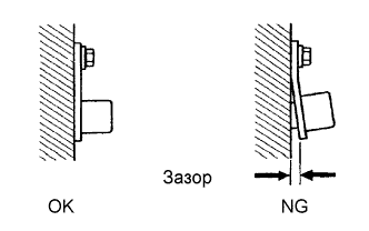 |
Check the VVT sensor installation.
|
| ||||
| OK | |
| 5.CHECK EXHAUST CAMSHAFT |
Check the teeth of the exhaust camshaft.
|
| ||||
| OK | |
| 6.REPLACE VVT SENSOR |
Replace the VVT sensor (see page Нажмите здесь).
| NEXT | |
| 7.CHECK WHETHER DTC OUTPUT RECURS (DTC P0365, P0367, P0368, P0390, P0392 AND/OR P0393) |
Connect the intelligent tester to the DLC3.
Turn the engine switch on (IG).
Turn the tester ON.
Clear DTCs
Start the engine.
Enter the following menus: Powertrain / Engine / DTC / Pending Codes.
Read DTCs.
| Display (DTC Output) | Proceed to |
| No output | A |
| P0365, P0367, P0368, P0390, P0392 and/ or P0393 | B |
|
| ||||
| A | ||
| ||
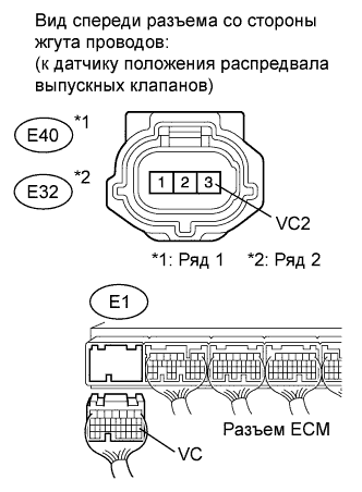
| 8.CHECK HARNESS AND CONNECTOR (VVT SENSOR FOR EXHAUST SIDE - ECM) |
 |
Disconnect the E32 or E40 VVT sensor for exhaust side connector.
Disconnect the E1 ECM connector.
Measure the resistance according to the value(s) in the table below.
| Tester Connection | Condition | Specified Condition |
| E40-3 (VC2) - E1-18 (VC) | Always | Below 1 Ω |
| E32-3 (VC2) - E1-18 (VC) | Always | Below 1 Ω |
| Tester Connection | Condition | Specified Condition |
| E40-3 (VC2) or E1-18 (VC) - Body ground | Always | 10 kΩ or higher |
| E32-3 (VC2) or E1-18 (VC) - Body ground | Always | 10 kΩ or higher |
|
| ||||
| OK | ||
| ||
