СИСТЕМА SFI > Выходная цепь VC |
| 1.CHECK MIL |
Check that Malfunction Indicator Lamp (MIL) lights up when turning the engine switch on (IG).
|
| ||||
| NG | |
| 2.CHECK CONNECTION BETWEEN INTELLIGENT TESTER AND ECM |
Connect the intelligent tester to the DLC3.
Turn the engine switch on (IG) and tester ON.
Check the communication between the tester and ECM.
| Result | Proceed to |
| Communication is possible | A |
| Communication is not possible | B |
|
| ||||
| B | |
| 3.CHECK MIL (THROTTLE BODY) |
Disconnect the throttle body connector.
Turn the engine switch on (IG).
Check the MIL.
| Result | Proceed to |
| MIL illuminates | A |
| MIL does not illuminate | B |
|
| ||||
| B | |
| 4.CHECK MIL (ACCELERATOR PEDAL) |
Disconnect the accelerator pedal position sensor connector.
Turn the engine switch on (IG).
Check the MIL.
| Result | Proceed to |
| MIL illuminates | A |
| MIL does not illuminate | B |
|
| ||||
| B | |
| 5.CHECK MIL (CRANKSHAFT POSITION SENSOR) |
Disconnect the crankshaft position sensor connector.
Turn the engine switch on (IG).
Check the MIL.
| Result | Proceed to |
| MIL illuminates | A |
| MIL does not illuminate | B |
|
| ||||
| B | |
| 6.CHECK MIL (CAMSHAFT POSITION SENSOR) |
Disconnect the camshaft position sensor connector.
Turn the engine switch on (IG).
Check the MIL.
| Result | Proceed to |
| MIL illuminates | A |
| MIL does not illuminate | B |
|
| ||||
| B | |
| 7.CHECK MIL (VVT SENSOR FOR INTAKE SIDE BANK 1) |
Disconnect the VVT sensor for intake camshaft bank 1 connector.
Turn the engine switch on (IG).
Check the MIL.
| Result | Proceed to |
| MIL illuminates | A |
| MIL does not illuminate | B |
|
| ||||
| B | |
| 8.CHECK MIL (VVT SENSOR FOR EXHAUST SIDE BANK 1) |
Disconnect the VVT sensor for exhaust side bank 1 connector.
Turn the engine switch on (IG).
Check the MIL.
| Result | Proceed to |
| MIL illuminates | A |
| MIL does not illuminate | B |
|
| ||||
| B | |
| 9.CHECK MIL (VVT SENSOR FOR INTAKE CAMSHAFT BANK 2) |
Disconnect the VVT sensor for intake camshaft bank 2 connector.
Turn the engine switch on (IG).
Check the MIL.
| Result | Proceed to |
| MIL illuminates | A |
| MIL does not illuminate | B |
|
| ||||
| B | |
| 10.CHECK MIL (VVT SENSOR FOR EXHAUST SIDE BANK 2) |
Disconnect the VVT sensor for exhaust side bank 2 connector.
Turn the engine switch on (IG).
Check the MIL.
| Result | Proceed to |
| MIL illuminates | A |
| MIL does not illuminate | B |
|
| ||||
| B | |
| 11.CHECK HARNESS AND CONNECTOR |
 |
Disconnect the throttle body connector.
Disconnect the accelerator pedal position sensor connector.
Disconnect the crankshaft position sensor connector.
Disconnect the camshaft position sensor connector.
Disconnect the VVT sensor connectors.
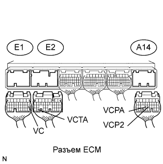
Disconnect the E1, E2 and A14 ECM connectors.
Measure the resistance according to the value(s) in the table below.
| Tester Connection | Condition | Specified Condition |
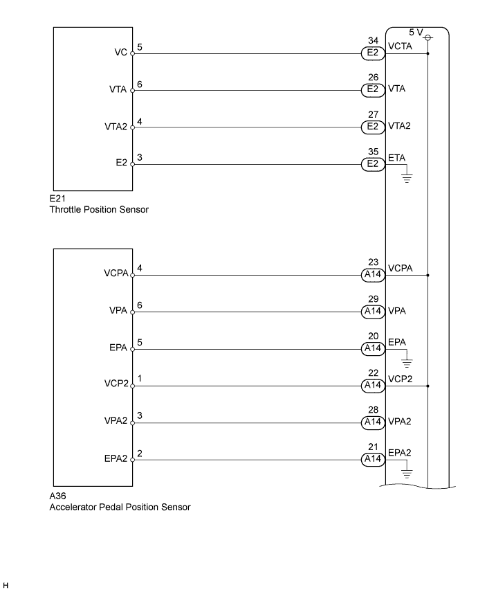
| E2-34 (VCTA) - Body ground | Always | 10 kΩ or higher |
| A14-23 (VCPA) - Body ground | Always | 10 kΩ or higher |
| A14-22 (VCP2) - Body ground | Always | 10 kΩ or higher |
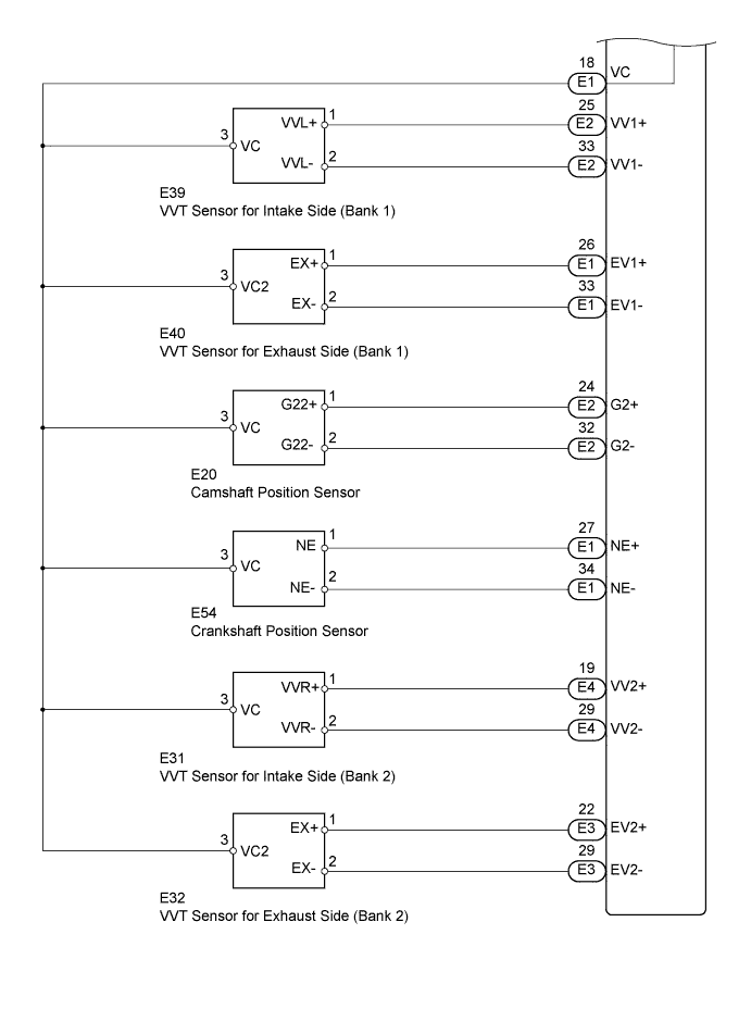
| E1-18 (VC) - Body ground | Always | 10 kΩ or higher |
|
| ||||
| OK | ||
| ||
