DTC U0101 Lost Communication with TCM |
| DTC No. | DTC Detection Condition | Trouble Area |
| U0101 |
|
|
| 1.CHECK ANY OTHER DTCS OUTPUT (IN ADDITION TO DTC U0101) |
Connect the intelligent tester to the DLC3.
Turn the engine switch on (IG).
Turn the tester ON.
Enter the following menus: Powertrain / Engine / DTC.
Read DTCs.
| Display (DTC output) | Proceed to |
| U0101 | A |
| U0101 and other DTCs | B |
|
| ||||
| A | |
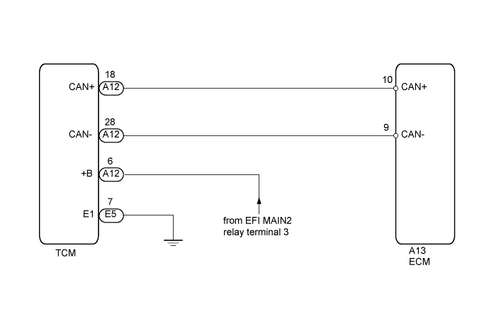
| 2.INSPECT TCM |
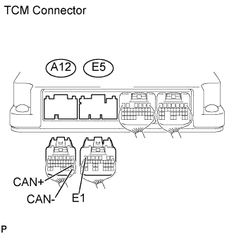 |
Disconnect the A12 TCM connector.
Turn the engine switch on (IG).
Measure the voltage according to the value(s) in the table below.
| Tester Connection | Switch Condition | Specified Condition |
| A12-6 (+B) - Body ground | Engine switch on (IG) | 11 to 14 V |
Measure the resistance according to the value(s) in the table below.
| Tester Connection | Condition | Specified Condition |
| E5-7 (E1) - Body ground | Always | Below 1 Ω |
|
| ||||
| OK | |
| 3.CHECK HARNESS AND CONNECTOR |
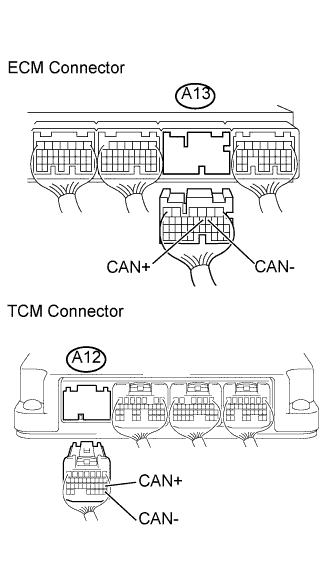 |
Disconnect the A13 ECM connector.
Disconnect the A12 TCM connector.
Measure the resistance according to the value(s) in the table below.
| Tester Connection | Condition | Specified Condition |
| A13-9 (CAN-) - A12-28 (CAN-) | Always | Below 1 Ω |
| A13-10 (CAN+) - A12-18 (CAN+) | Always | Below 1 Ω |
| Tester Connection | Condition | Specified Condition |
| A13-9 (CAN-) or A12-28 (CAN-) - Body ground | Always | 10 kΩ or higher |
| A13-10 (CAN+) - A12-18 (CAN+) - Body ground | Always | 10 kΩ or higher |
|
| ||||
| OK | |
| 4.REPLACE ECM |
Replace the ECM (see page Нажмите здесь).
| NEXT | |
| 5.CHECK WHETHER DTC OUTPUT RECURS (DTC U0101) |
Connect the intelligent tester to the DLC3.
Turn the engine switch on (IG) and turn the tester ON.
Enter the following menus: Powertrain / Engine / DTC.
Read DTCs.
| Display (DTC output) | Proceed to |
| No output | A |
| U0101 | B |
|
| ||||
| A | ||
| ||
