СИСТЕМА ПОСАДКИ И ЗАПУСКА > КОНТАКТЫ ЭБУ |
| CHECK MAIN BODY ECU |
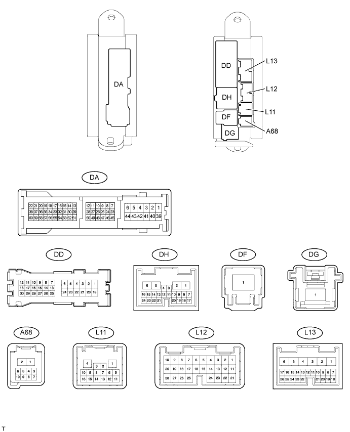
Disconnect the A68, L13 and DA main body ECU connectors.
Measure the voltage and resistance according to the value(s) in the table below.
| Terminal No. (Symbols) | Wiring Color | Terminal Description | Condition | Specified Condition |
| L13-6 (AM1) - Body ground | W - Body ground | +B power supply | Always | 11 to 14 V |
| L12-1 (AM2) - Body ground | W - Body ground | +B power supply | Always | 11 to 14 V |
| L13-17 (SSW1) - Body ground | W - Body ground | Engine switch 1 input | Engine switch pushed | Below 1 Ω |
| L13-17 (SSW1) - Body ground | W - Body ground | Engine switch 1 input | Engine switch not pushed | 10 kΩ or higher |
| L13-16 (SSW2) - Body ground | L - Body ground | Engine switch 2 input | Engine switch pushed | Below 1 Ω |
| L13-16 (SSW2) - Body ground | L - Body ground | Engine switch 2 input | Engine switch not pushed | 10 kΩ or higher |
| DA-40 (GND1) - Body ground | W-B - Body ground | Ground | Always | Below 1 Ω |
| DA-23 or DA-52 (LIN1) - Body ground | O - Body ground | LIN line | Always | 10 kΩ or higher |
Reconnect the A68, L13 and DA main body ECU connectors.
Measure the voltages according to the value(s) in the table below.
| Terminal No. (Symbols) | Wiring Color | Terminal Description | Condition | Specified Condition |
| L13-22 (ACCD) - DA-40 (GND1) | G - W-B | D-ACC relay drive signal | Engine switch on (ACC) | 11 to 14 V |
| L13-22 (ACCD) - DA-40 (GND1) | G - W-B | D-ACC relay drive signal | Engine switch off | Below 1 V |
| L12-11 (IG2D) - DA-40 (GND1) | P - W-B | IG2 relay drive signal | Engine switch on (IG) | 11 to 14 V |
| L12-11 (IG2D) - DA-40 (GND1) | P - W-B | IG2 relay drive signal | Engine switch on (ACC) | Below 1 V |
| L13-19 (SLR+) - DA-40 (GND1) | SB - W-B | Steering lock power supply | Steering lock motor operating | Below 1 V |
| L13-19 (SLR+) - DA-40 (GND1) | SB - W-B | Steering lock power supply | Steering lock motor not operating | 11 to 14 V |
| L13-18 (SLP) - DA-40 (GND1) | LG - W-B | Steering lock actuator position signal | Steering lock locked | 11 to 14 V |
| L13-18 (SLP) - DA-40 (GND1) | LG - W-B | Steering lock actuator position signal | Steering lock released | Below 1 V |
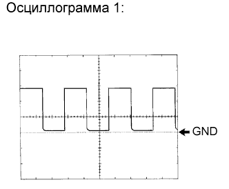
| L11-9 (SPD) - DA-40 (GND1) | V - W-B | Speed signal from combination meter | Engine switch on (IG), rotate driving wheel slowly | Pulse generation (see waveform 1) |
| L11-8 (TACH) - DA-40 (GND1) | B - W-B | Tachometer signal | Engine running | Pulse generation (see waveform 2) |
| A68-4 (STSW) - DA-40 (GND1) | B - W-B | Starter activation request signal | Brake pedal depressed with shift lever in P or N, engine switch pushed once | 11 to 14 V* |
| L13-8 (STR) - DA-40 (GND1) | L - W-B | Park / neutral position switch | Shift lever in P or N | Below 1 V |
| A68-6 (STR2) - DA-40 (GND1) | BR - W-R | Starter signal | Brake pedal depressed with shift lever in P or N, engine switch pushed once | 11 to 14 V* |
| L13-15 (INDS) - DA-40 (GND1) | B - W-B | Vehicle condition signal | Brake pedal depressed with shift lever in P or N, engine switch off, on (ACC, IG) | 9 to 14 V |
| L13-14 (INDW) - DA-40 (GND1) | P - W-B | Vehicle condition signal | Brake pedal released with shift lever in P or N, engine switch off, on (ACC, IG) | 9 to 14 V |
| L13-25 (SWIL) - DA-40 (GND1) | R - W-B | Illumination signal | Light control switch TAIL or HEAD | 11 to 14 V |
| DH-15 (STP) - DA-40 (GND1) | L - W-B | Stop light switch signal | Brake pedal depressed | 11 to 14 V |
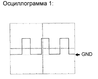 |
Using an oscilloscope, check waveform 1.
| Item | Content |
| Terminal No. (Symbols) | L11-9 (SPD) - DA-40 (GND1) |
| Tool setting | 5 V/DIV., 10 msec./DIV. |
| Condition | Driving at approx. 20 km/h (12 mph) |
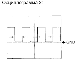 |
Using an oscilloscope, check waveform 2.
| Item | Content |
| Terminal No. (Symbols) | L11-8 (TACH) - DA-40 (GND1) |
| Tool setting | 5 V/DIV., 10 msec./DIV. |
| Condition | Engine idling |
| CHECK CERTIFICATION ECU |
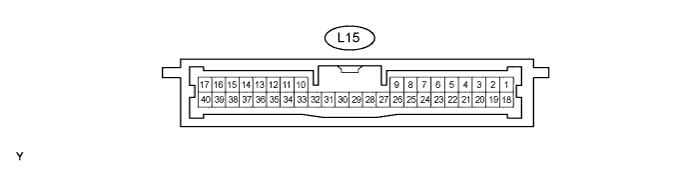
Disconnect the L15 certification ECU connector.
Measure the voltage and resistance according to the value(s) in the table below.
| Terminal No. (Symbols) | Wiring Color | Terminal Description | Condition | Specified Condition |
| L15-1 (+B1) - Body ground | L - Body ground | +B power supply | Always | 11 to 14 V |
| L15-18 (IG) - Body ground | L - Body ground | Ignition power supply | Engine switch on (IG) | 11 to 14 V |
| L15-18 (IG) - Body ground | L - Body ground | Ignition power supply | Engine switch off | Below 1 V |
| L15-10 (LIN) - Body ground | O - Body ground | LIN line | Always | 10 kΩ or higher |
| L15-17 (E) - Body ground | W-B - Body ground | Ground | Always | Below 1 Ω |
| CHECK ECM |
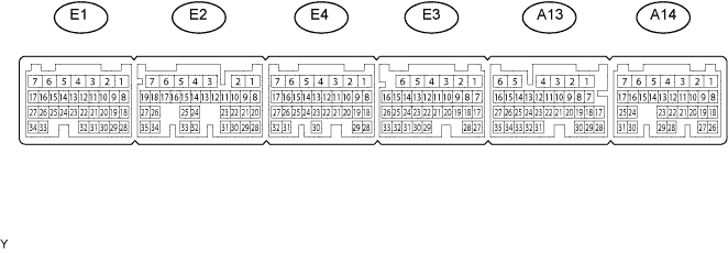
Disconnect the A13, A14, E2 and E3 ECM connectors.
Measure the voltage and resistance according to the value(s) in the table below.
| Terminal No. (Symbols) | Wiring Color | Terminal Description | Condition | Specified Condition |
| A14-7 (BATT) - E3-1 (E1) | B - W-B | Battery (for measuring battery voltage and for ECM memory) | Always | 11 to 14 V |
| A13-1 (+B) - E3-1 (E1) | BW - W-B | Power source of ECM | Engine switch on (IG) | 11 to 14 V |
| A14-8 (IGSW) - E3-1 (E1) | R - BR | Engine switch signal | Always | 11 to 14 V |
| E3-1 (E1) - Body ground | W-B - Body ground | Ground | Always | Below 1 Ω |
| E2-1 (E02) - Body ground | W-B - Body ground | Ground | Always | Below 1 Ω |
| E3-4 (E04) - Body ground | W-B - Body ground | Ground | Always | Below 1 Ω |
| E2-2 (E01) - Body ground | W-B - Body ground | Ground | Always | Below 1 Ω |
| A13-5 (E03) - Body ground | W-B - Body ground | Ground | Always | Below 1 Ω |
Reconnect the A13, A14, E2 and E3 ECM connectors.
Measure the voltage according to the value(s) in the table below.
| Terminal No. (Symbols) | Wiring Color | Terminal Description | Condition | Specified Condition |
| A13-20 (STA) - E3-1 (E1) | Y - W-B | Starter relay operation signal | Cranking | 5.5 V or more |
| A13-19 (ACCR) - E3-1 (E1) | G - W-B | D-ACC relay cut signal (output) | Engine switch on (IG) → Cranking | 11 to 14 V → Below 1 V |
| A14-15 (TACH) - E3-1 (E1) | R - W-B | Engine revolution signal (output) | Idling | Pulse generation (see waveform 1) |
| A14-2 (STAR) - E3-1 (E1) | BR - W-B | Starter relay drive signal | Cranking | 11 to 14 V |
 |
Using an oscilloscope, check waveform 1.
| Item | Content |
| Terminal No. (Symbols) | A14-15 (TACH) - E3-1 (E1) |
| Tool setting | 5 V/DIV., 10 msec./DIV. |
| Condition | Engine idling |
| CHECK STEERING LOCK ECU |
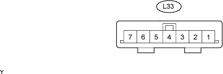
Disconnect the L33 steering lock ECU connector.
Measure the voltage and resistance according to the value(s) in the table below.
| Terminal No. (Symbols) | Wiring Color | Terminal Description | Condition | Specified Condition |
| L33-7 (B) - Body ground | P - Body ground | +B power supply | Always | 11 to 14 V |
| L33-6 (IG2) - Body ground | L - Body ground | Ignition power supply | Engine switch on (IG) | 11 to 14 V |
| L33-6 (IG2) - Body ground | L - Body ground | Ignition power supply | Engine switch off | Below 1 V |
| L33-1 (GND) - Body ground | W-B - Body ground | Ground | Always | Below 1 Ω |
| L33-2 (SGND) - Body ground | BR - Body ground | Ground | Always | Below 1 Ω |
