DTC P0102 Mass Air Flow Circuit Low |
DTC P0103 Mass Air Flow Circuit High |
DTC P010C Mass or Volume Air Flow "A" Circuit Low Input |
DTC P010D Mass or Volume Air Flow "A" Circuit High Input |
| DTC No. | DTC Detection Condition | Trouble Area |
| P0102 P010C | Open in Mass Air Flow (MAF) meter circuit for 3 seconds |
|
| P0103 P010D | Short in Mass Air Flow (MAF) meter circuit for 3 seconds |
|
| Mass Air Flow Rate (g/sec.) | Malfunctions |
| Approximately 0.0 |
|
| 271.0 or more |
|
| 1.READ VALUE USING INTELLIGENT TESTER (MASS AIR FLOW RATE) |
Connect the intelligent tester to the DLC3.
Turn the tester ON.
Wait 30 seconds with the engine stopped.
Enter the following menus: Powertrain / Engine / Data List / MAF Bank 1 or MAF Bank 2.
Read the values displayed on the tester.
| Mass Air Flow Rate (g/sec.) | Proceed to |
| 0.0 | A |
| 0.26 or more | B |
| Between 1.0 and 0.25* | C |
|
| ||||
|
| ||||
| A | |
| 2.INSPECT MASS AIR FLOW METER (POWER SOURCE VOLTAGE) |
 |
Disconnect the E13 or E22 MAF meter connector.
Turn the engine switch on (IG).
Measure the voltage according to the value(s) in the table below.
| Tester Connection | Switch Condition | Specified Condition |
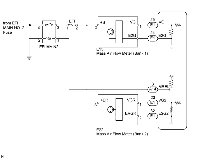
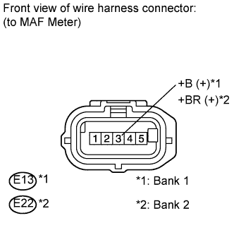
| E13-3 (+B) - Body ground | Engine switch on (IG) | 11 to 14 V |
| E22-3 (+B) - Body ground | Engine switch on (IG) | 11 to 14 V |
|
| ||||
| OK | |
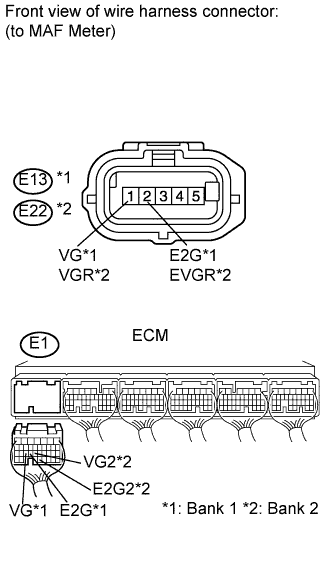
| 3.INSPECT ECM (VG VOLTAGE) |
 |
Start the engine.
Measure the voltage according to the value(s) in the table below.
| Tester Connection | Condition | Specified Condition |
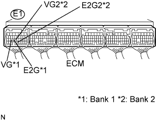
| E1-25 (VG) - E1-24 (E2G) | Engine idling | 0.5 to 3.0 V |
| E1-23 (VG2) - E1-32 (E2G2) | Engine idling | 0.5 to 3.0 V |
|
| ||||
| NG | |
| 4.CHECK HARNESS AND CONNECTOR (MASS AIR FLOW METER - ECM) |
 |
Disconnect the E13 or E22 MAF meter connector.
Disconnect the E1 ECM connector.
Measure the resistance according to the value(s) in the table below.
| Tester Connection | Condition | Specified Condition |
| E13-1 (VG) - E1-25 (VG) | Always | Below 1 Ω |
| E13-2 (E2G) - E1-24 (E2G) | Always | Below 1 Ω |
| E22-1 (VGR) - E1-23 (VG2) | Always | Below 1 Ω |
| E22-2 (EVGR) - E1-32 (E2G2) | Always | Below 1 Ω |
| Tester Connection | Condition | Specified Condition |
| E13-1 (VG) or E1-25 (VG) - Body ground | Always | 10 kΩ or higher |
| E22-1 (VGR) or E1-23 (VG2) - Body ground | Always | 10 kΩ or higher |
|
| ||||
| OK | ||
| ||
| 5.CHECK HARNESS AND CONNECTOR (MASS AIR FLOW METER - EFI FUSE) |
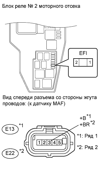 |
Remove the EFI fuse from the engine room No. 2 relay block.
Inspect the fuse.
Measure the resistance of the EFI fuse.
Disconnect the E13 or E22 MAF meter connector.
Measure the resistance according to the value(s) in the table below.
| Tester Connection | Condition | Specified Condition |
| E13-3 (+B) - EFI fuse terminal 2 | Always | Below 1 Ω |
| E22-3 (+B) - EFI fuse terminal 2 | Always | Below 1 Ω |
| Tester Connection | Condition | Specified Condition |
| E13-3 (+B) or EFI fuse terminal 2 - Body ground | Always | 10 kΩ or higher |
| E22-3 (+B) or EFI fuse terminal 2 - Body ground | Always | 10 kΩ or higher |
|
| ||||
| OK | ||
| ||
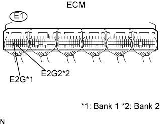
| 6.INSPECT ECM (SENSOR GROUND) |
 |
Measure the resistance according to the value(s) in the table below.
| Tester Connection | Condition | Specified Condition |
| E1-24 (E2G) - Body ground | Always | Below 1 Ω |
| E1-32 (E2G2) - Body ground | Always | Below 1 Ω |
|
| ||||
| OK | |
| 7.CHECK HARNESS AND CONNECTOR (MASS AIR FLOW METER - ECM) |
|
Disconnect the E13 or E22 MAF meter connector.
Disconnect the E1 ECM connector.
Measure the resistance according to the value(s) in the table below.
| Tester Connection | Condition | Specified Condition |
| E13-1 (VG) - E1-25 (VG) | Always | Below 1 Ω |
| E13-2 (E2G) - E1-24 (E2G) | Always | Below 1 Ω |
| E22-1 (VGR) - E1-23 (VG2) | Always | Below 1 Ω |
| E22-2 (EVGR) - E1-32 (E2G2) | Always | Below 1 Ω |
| Tester Connection | Condition | Specified Condition |
| E13-1 (VG) or E1-25 (VG) - Body ground | Always | 10 kΩ or higher |
| E22-1 (VGR) or E1-23 (VG2) - Body ground | Always | 10 kΩ or higher |
|
| ||||
| OK | ||
| ||
