СТАРТЕР (для 2,0 кВт) > УСТАНОВКА |
| 1. INSTALL STARTER ASSEMBLY |
 |
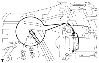
Install the flywheel housing side cover.
 |
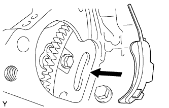
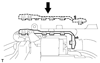
Install the starter terminal lower cover with the nut.
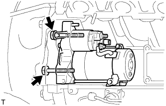 |
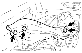
Install the starter with the 2 bolts.
 |
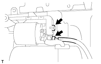 |
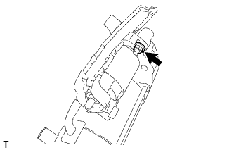
Install the wire harness with the nut.
Connect the starter connector.
 |
Install the starter terminal upper cover.
| 2. INSTALL NO. 3 EXHAUST MANIFOLD HEAT INSULATOR |
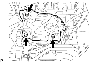 |
Install the No. 3 exhaust manifold heat insulator with the 3 bolts.
| 3. INSTALL EXHAUST MANIFOLD SUB-ASSEMBLY RH |
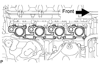 |
Install a new gasket as shown in the illustration.
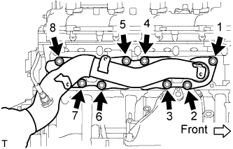 |
Install the exhaust manifold to the cylinder head with the new 8 nuts in the order shown in the illustration.
| 4. INSTALL NO. 1 EXHAUST MANIFOLD HEAT INSULATOR |
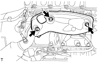 |
Install the heat insulator with the 3 bolts.
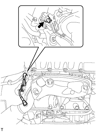 |
Connect the sensor connector.
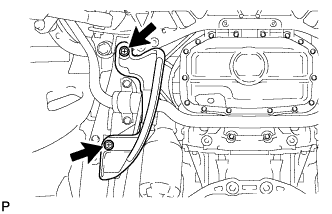
| 5. INSTALL ENGINE OIL LEVEL DIPSTICK GUIDE |
Apply a light coat of engine oil to a new O-ring.
Install the new O-ring to the guide.
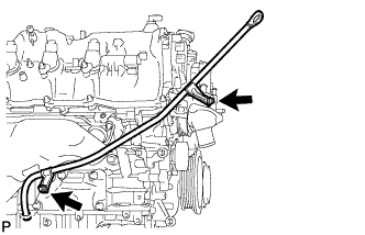 |
Install the dipstick guide with the 2 bolts.
Install the dipstick.
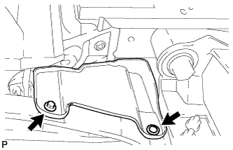
| 6. INSTALL FRONT SUSPENSION MEMBER REINFORCEMENT RH |
 |
Install the front suspension member reinforcement with the 4 bolts.
| 7. INSTALL ENGINE UNDER COVER RH |
 |
Install the engine under cover RH with the clip and screw.
| 8. CONNECT FRONT STABILIZER BAR |
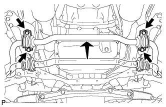 |
Подсоедините штангу стабилизатора к задней скобе и закрепите ее 4 болтами.
| 9. INSTALL ENGINE UNDER COVER REAR LH |
 |
Установите левую заднюю защиту картера двигателя и закрепите ее 2 винтами.
| 10. INSTALL ENGINE UNDER COVER REAR RH |
| 11. INSTALL FRONT EXHAUST PIPE ASSEMBLY |
Install the front exhaust pipe (see page Нажмите здесь).
| 12. INSTALL GENERATOR ASSEMBLY |
Install the generator (see page Нажмите здесь).
| 13. CONNECT CABLE TO NEGATIVE BATTERY TERMINAL |
| 14. INSTALL COWL TOP VENTILATOR LOUVER RH |
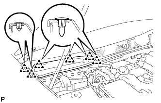 |
Install the 6 clips and cowl top ventilator louver RH.
| 15. PERFORM INITIALIZATION |
Perform initialization (see page Нажмите здесь).
