СТАРТЕР (для 1,6 кВт) > ПРОВЕРКА |
| 1. INSPECT STARTER ASSEMBLY |
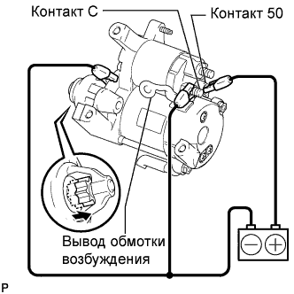 |
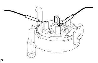
Perform the pull-in test.
Disconnect the field coil wire from terminal C.
Connect the battery to the magnetic switch as shown in the illustration. Check that the clutch pinion gear moves outward.
If the clutch pinion gear does not move outward, replace the magnetic switch.
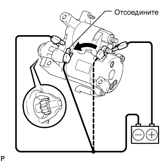 |
Perform the hold-in test.
Disconnect the negative (-) terminal lead from terminal C with the condition specified in the pull-in test above being maintained. Check that the pinion gear remains out.
If the clutch pinion gear moves inward, replace the magnetic switch.
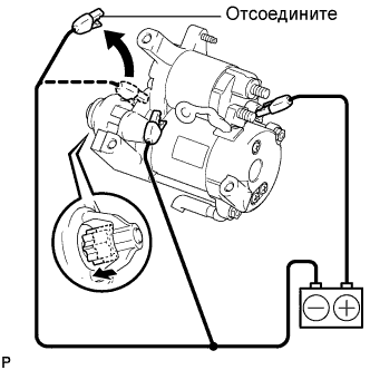 |
Inspect the clutch pinion gear return.
Disconnect the negative (-) lead from the starter body. Check that the clutch pinion gear moves inward.
If the clutch pinion gear does not move inward, replace the magnetic switch assembly.
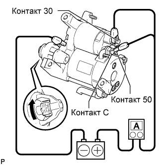 |
Perform the no-load performance test.
Connect the field coil wire to terminal C with the nut. Make sure that the lead is not grounded.
Clamp the starter in a vise.
Connect the battery and an ammeter to the starter as shown in the illustration.
Check that the starter rotates smoothly and steadily while the pinion gear is moving out.
Then measure the current.
| 2. INSPECT STARTER ARMATURE ASSEMBLY |
Inspect the resistance of the commutator.
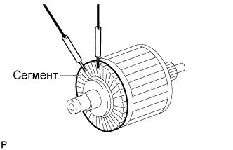 |
Using an ohmmeter, measure the resistance between the segments of the commutator.
| Tester Connection | Specified Condition |
| Segment - Segment | Below 1 Ω |
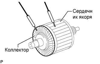 |
Using an ohmmeter, measure the resistance between the commutator and armature coil core.
| Tester Connection | Specified Condition |
| Commutator - Armature | 10 kΩ or higher |
Check the surface of the commutator for dirt or burns.
If the surface is dirty or burnt, smooth it with 400-grit sandpaper or trim it on a lathe.
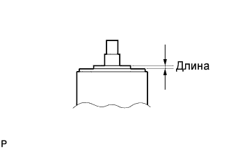 |
Using vernier calipers, measure the commutator length.
| 3. INSPECT STARTER COMMUTATOR END FRAME ASSEMBLY |
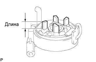 |
Using vernier calipers, measure the brush length.
 |
Using an ohmmeter, measure the resistance between the positive (+) and negative (-) brushes.
| Tester Connection | Specified Condition |
| Positive (+) brush - Negative (-) brush | 10 kΩ or higher |
| 4. INSPECT STARTER CENTER BEARING CLUTCH SUB-ASSEMBLY |
Check the gear teeth on the planetary gears, internal gear and starter clutch for wear or damage.
If any of the gears is damaged, replace the center bearing clutch sub-assembly.
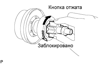 |
Check the starter clutch pinion gear.
Turn the clutch pinion gear clockwise and check that it turns freely. Try to turn the clutch pinion gear counterclockwise and check that it locks.
If necessary, replace the center bearing clutch sub-assembly.
| 5. INSPECT REPAIR SERVICE STARTER KIT |
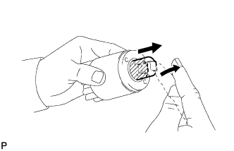 |
Check the plunger.
Push in the plunger and check that it returns quickly to its original position.
If necessary, replace the repair service starter kit.
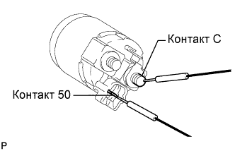 |
Using an ohmmeter, measure the resistance between terminal 50 and C.
| Tester Connection | Specified Condition |
| Terminal 50 - Terminal C | Below 1 Ω |
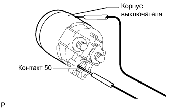 |
Using an ohmmeter, measure the resistance between terminal 50 and the switch body.
| Tester Connection | Specified Condition |
| Terminal 50 - Switch body | Below 2 Ω |
