ДВИГАТЕЛЬ > УСТАНОВКА |
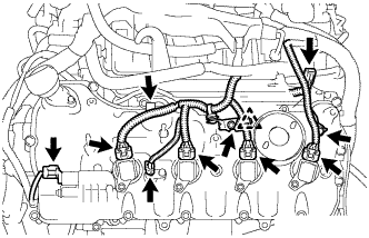
| 1. INSTALL IGNITION COIL |
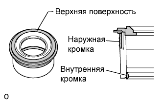 |
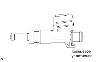
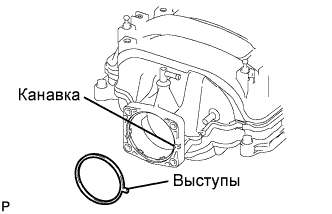
Perform a visual inspection on the spark plug tube gasket
| Inspection Area | Inspection Result |
| Upper surface | No scratches or deformation |
| Outer lip | No scratches or deformation |
| Inner lip | No scratches |
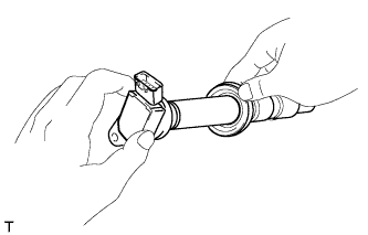 |
Set each spark plug tube gasket on each ignition coil.
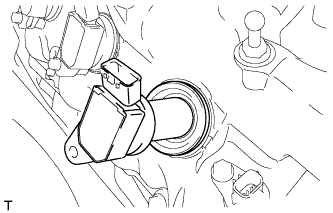 |
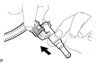
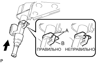
After installing each spark plug tube gasket, securely insert each ignition coil.
 |
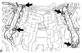
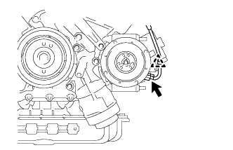
Install the 8 bolts.
Connect the 8 ignition coil connectors.
| 2. INSTALL KNOCK SENSOR |
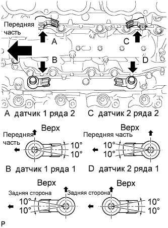 |
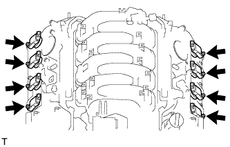
Install the 4 knock sensors with the 4 bolts so that the sensors are angled as shown in the illustration.
Connect the 4 knock sensor connectors.
| 3. INSTALL ENGINE COOLANT TEMPERATURE SENSOR |
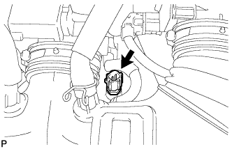 |
Install a new gasket to the engine coolant temperature sensor.
Install the engine coolant temperature sensor.
Connect the engine coolant temperature sensor connector.
| 4. INSTALL ENGINE OIL LEVEL SENSOR |
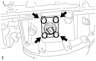 |
Install the oil level sensor with the 4 bolts.
| 5. INSTALL ENGINE OIL PRESSURE SWITCH ASSEMBLY |
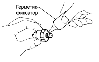 |
Apply adhesive to 2 or 3 threads of the switch.
 |
Using a 24 mm deep socket wrench, install the switch.
Connect the switch connector.
| 6. INSTALL WATER INLET HOUSING |
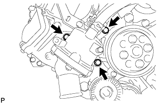 |
Install a new gasket to the water pump.
Install the water inlet housing with the 3 bolts.
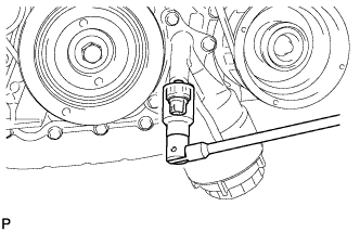
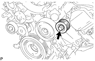
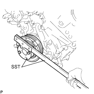
| 7. INSTALL WATER PUMP PULLEY |
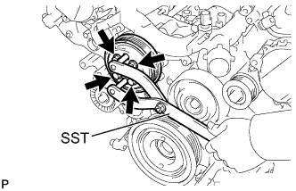 |
Temporarily install the pulley with the 4 bolts.
Using SST, hold the pulley and tighten the 4 bolts.
| 8. INSTALL NO. 1 IDLER PULLEY SUB-ASSEMBLY |
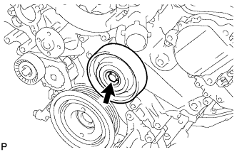 |
Install the bolt and idler pulley.
| 9. INSTALL NO. 2 IDLER PULLEY SUB-ASSEMBLY |
 |
Install the bolt and idler pulley.
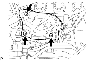
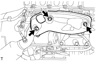
| 10. INSTALL NO. 4 ENGINE COVER SUB-ASSEMBLY |
 |
Install the engine cover.
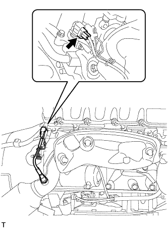
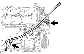
| 11. INSTALL ENGINE WIRE |
 |
Install the engine wire with the bolt.
Connect the 4 knock sensor connectors.
| 12. INSTALL SEPARATOR CASE |
 |
Install the case separator with the 4 bolts.
| 13. INSTALL FUEL INJECTOR ASSEMBLY |
 |
Apply gasoline to a new O-ring and install it to the injector.
 |
Connect the connector to the injector.
 |
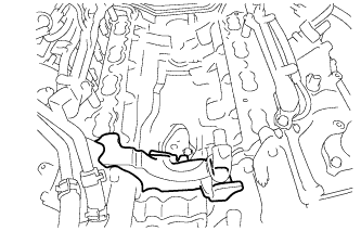
Install the injector to the delivery pipe as shown in the illustration.
| 14. INSTALL FUEL DELIVERY PIPE |
 |
Connect the 4 wire harness clamps.
Install the 4 delivery pipe spacers and 8 insulators to the intake manifold.
Install the 2 delivery pipes (with injector) to the intake manifold.
 |
Install the 4 bolts.
 |
Connect the 2 connectors.
| 15. INSTALL FUEL TUBE SUB-ASSEMBLY |
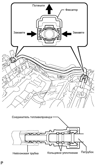 |
Push in the tube connector to the pipe until the tube connector makes a "click" sound.
Push down on the retainer to lock it in place.
| 16. INSTALL NO. 2 ENGINE COVER SUB-ASSEMBLY LH |
 |
Install the No. 2 engine cover sub-assembly LH.
| 17. INSTALL NO. 3 ENGINE COVER |
 |
Install the No. 3 engine cover.
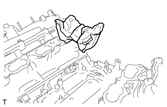
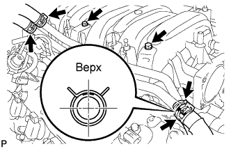
| 18. INSTALL INTAKE MANIFOLD |
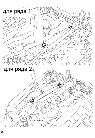
Install 2 new gaskets to the intake manifold.
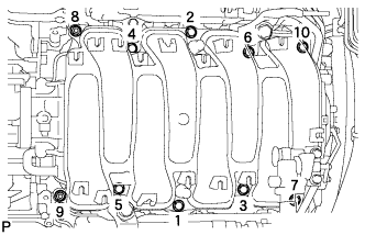 |
Temporarily install the intake manifold with the 2 nuts and 8 bolts. Then tighten the 2 nuts and 8 bolts uniformly in the order shown in the illustration.
 |
Connect the No.1 ventilation hose to the intake manifold.
| 19. INSTALL THROTTLE BODY ASSEMBLY |
 |
Install a new gasket to the intake manifold.
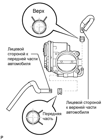 |
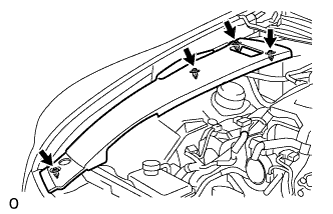
Connect the No. 4 water by-pass hose and No. 5 water by-pass hose to the throttle body.
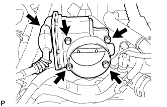 |
Install the throttle body with the 4 bolts.
Connect the throttle motor connector.
| 20. INSTALL VENTILATION HOSE |
| 21. INSTALL WATER BY-PASS PIPE SUB-ASSEMBLY |
 |
Install the water by-pass pipe to the intake manifold with the 2 bolts.
Connect the heater water inlet hose, heater water outlet hose, water inlet hose, and No. 3 water bypass hose to the water by-pass pipe with the 4 clamps.
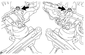
| 22. INSTALL FRONT NO. 1 ENGINE MOUNTING BRACKET RH |
 |
Install the mounting bracket with the 6 bolts.
| 23. INSTALL FRONT NO. 1 ENGINE MOUNTING BRACKET LH |
 |
Install the mounting bracket with the 6 bolts.
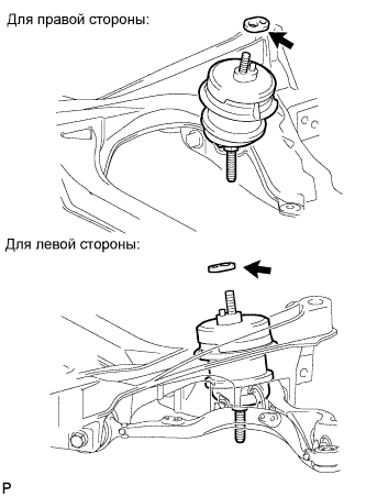
| 24. INSTALL ENGINE MOUNTING DAMPER |
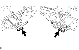 |
Install the 2 mounting dampers with the 2 nuts.
| 25. INSTALL GENERATOR ASSEMBLY |
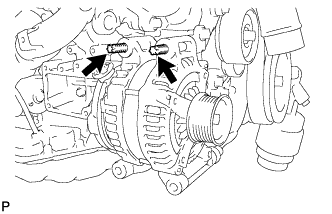 |
Using an E8 "TORX" socket wrench, set the generator with the 2 stud bolts.
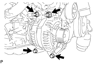 |
Install the generator with the 2 bolts and 2 nuts.
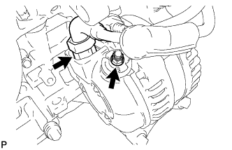 |
Connect the generator connector.
Connect the harness to the +B terminal with the nut.
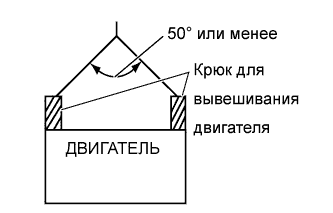
| 26. REMOVE ENGINE STAND |
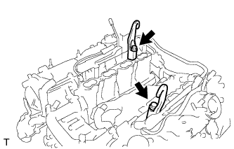 |
Install the 2 engine hangers with the 2 bolts as shown in the illustration.
Attach an engine sling device and hang the engine with a chain block.
 |
Remove the bolts and engine assembly from the engine stand.
| 27. INSTALL ENGINE MOUNTING SPACER |
 |
Install the 2 mounting spacers to the engine mounting insulator.
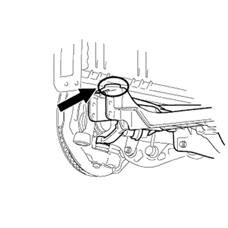
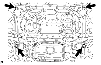
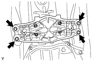
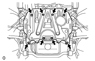
| 28. INSTALL FRONT SUSPENSION CROSSMEMBER SUB-ASSEMBLY |
 |
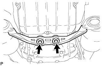
Install the crossmember with the 2 nuts.
| 29. INSTALL DRIVE PLATE AND RING GEAR SUB-ASSEMBLY |
 |
Using SST, hold the crankshaft.
Install the sensor rotor, ring gear and spacer plate on the crankshaft.
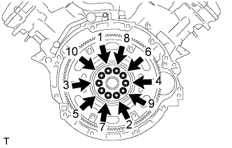 |
Uniformly install and tighten 10 new bolts in the sequence shown in the illustration.
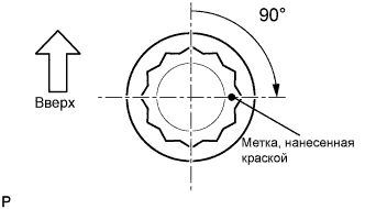 |
Mark the upside of each flywheel installation bolt with paint.
Retighten the flywheel installation bolts by 90° as shown.
Check that the painted marks are now at a 90° angle to the upside.
| 30. INSTALL AUTOMATIC TRANSMISSION ASSEMBLY |
 |
Установите автоматическую трансмиссию на двигатель и закрепите ее 10 болтами.
 |
Заверните 6 крепежных болтов муфты гидротрансформатора.
 |
Установите боковую крышку картера маховика.
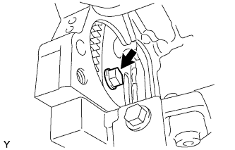
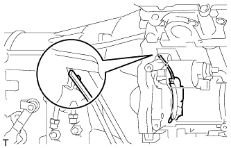
| 31. INSTALL STARTER ASSEMBLY |
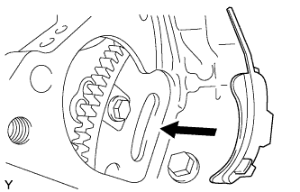 |
Install the flywheel housing side cover.
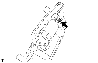 |
Install the starter terminal lower cover with the nut.
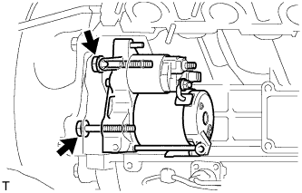 |
Install the starter with the 2 bolts.
 |
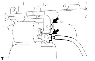 |
Install the wire harness with the nut.
Connect the starter connector.
 |
Install the starter terminal upper cover.
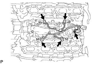
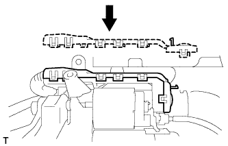
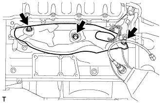
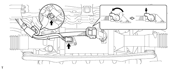
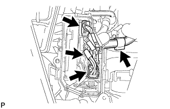
| 32. INSTALL ENGINE WIRE |
 |
Install the engine wire with the 4 nuts.
Connect the clamp and 2 clamp brackets with the 2 bolts.
Connect the intake air control valve actuator connector.
Connect the No. 1 vacuum switching valve connector.
Connect the throttle body connectors.
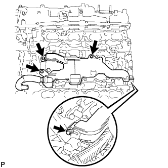
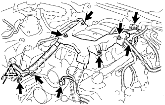
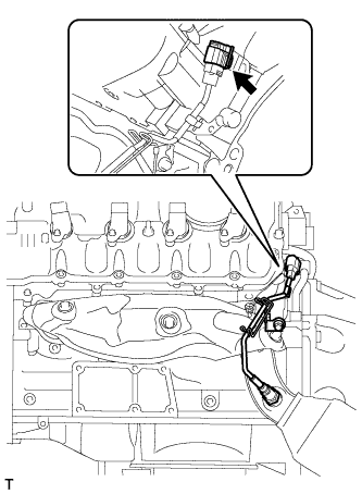
for Engine RH Side:
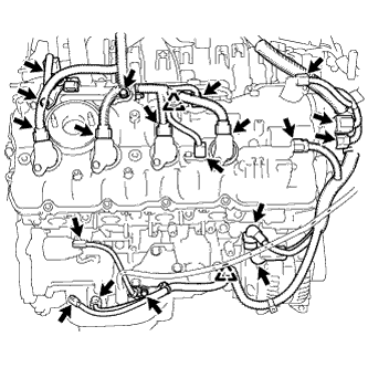 |
Connect the 2 clamps and install the 3 clamp brackets with the 3 bolts.
Connect the engine oil level sensor connector.
Connect the crankshaft position sensor connector.
Connect the starter connector and starter wire with the nut.
Connect the generator connector and generator wire with the nut.
Connect the camshaft position sensor connector.
Connect the engine wire connector.
Connect the 2 camshaft timing control motor connectors. (for Bank 2)
Connect the 2 VVT sensor connectors.
Connect the 4 ignition coil connectors.
Connect the camshaft timing control valve connector.
for Engine LH Side:
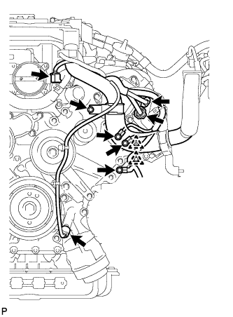 |
Install the clamp bracket with the bolt.
Connect the 3 clamps and 3 ground wires with the 3 bolts.
Connect the 2 camshaft timing control motor connectors. (for Bank 1)
Connect the oil pressure sensor connector.
Connect the engine coolant temperature sensor connector.
 |
Connect the clamp and install the 2 clamp brackets with the 2 bolts.
Connect the No. 8 engine wire connector.
Connect the 2 VVT sensor connectors.
Connect the 4 ignition coil connectors.
Connect the camshaft timing control valve connector.
| 33. INSTALL NO. 3 EXHAUST MANIFOLD HEAT INSULATOR |
 |
Install the No. 3 exhaust manifold heat insulator with the 3 bolts.
| 34. INSTALL OIL COOLER TUBE |
Временно закрепите впускной и выпускной патрубки масляного радиатора.
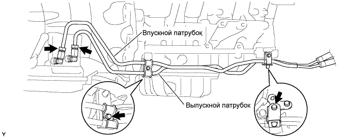
Установите 2 зажима и закрепите их 2 болтами.
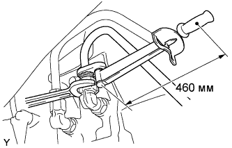 |
Используя SST, затяните гайки штуцеров впускного и выпускного патрубков масляного радиатора.
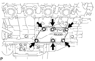
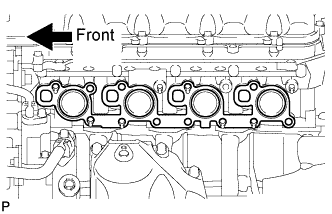
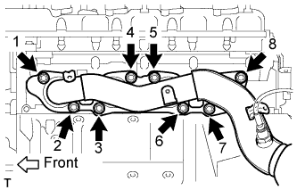
| 35. INSTALL EXHAUST MANIFOLD SUB-ASSEMBLY (for Bank 2) |
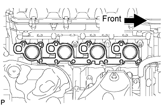 |
Install a new gasket as shown in the illustration.
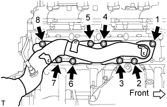 |
Install the exhaust manifold to the cylinder head with the new 8 nuts in the order shown in the illustration.
| 36. INSTALL NO. 1 EXHAUST MANIFOLD HEAT INSULATOR |
 |
Install the heat insulator with the 3 bolts.
 |
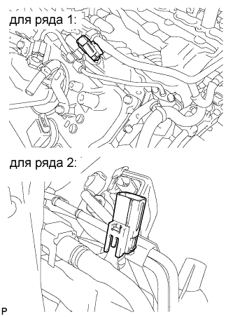
Connect the sensor connector.
| 37. INSTALL OIL LEVEL DIPSTICK GUIDE |
Apply a light coat of engine oil to a new O-ring.
Install the new O-ring to the guide.
 |
Install the dipstick guide with the 2 bolts.
Install the dipstick.
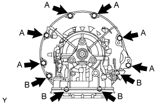
| 38. INSTALL ENGINE AND TRANSMISSION |
Place the engine on an engine lifter.
Remove the 2 bolts and 2 engine hangers.
Operate the engine lifter, then install the engine to the vehicle.
 |
Align the crossmember to the marks on the vehicle, and temporarily install the engine and transmission with crossmember with the 4 bolts.
 |
Tighten the 4 bolts.
 |
Install the 4 engine rear mounting member's bolts.
| 39. CONNECT FLOOR SHIFT GEAR SHIFTING ROD SUB-ASSEMBLY |
 |
Временно подсоедините тягу механизма переключения к шарниру соединительной тяги с помощью гайки.
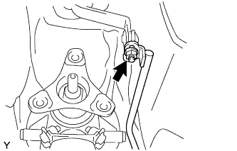
| 40. CONNECT FRONT NO. 2 LOWER SUSPENSION ARM SUB-ASSEMBLY |
Connect the front No. 2 lower suspension arm (see page Нажмите здесь).
| 41. CONNECT COOLER COMPRESSOR ASSEMBLY |
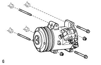 |
Connect the cooler compressor with the 2 stud bolts, 2 nuts and 2 bolts.
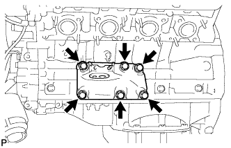
| 42. INSTALL EXHAUST MANIFOLD SUB-ASSEMBLY (for Bank 1) |
 |
Install a new gasket as shown in the illustration.
 |
Install the exhaust manifold to the cylinder head with the new 8 nuts in the order shown in the illustration.
| 43. INSTALL NO. 2 EXHAUST MANIFOLD HEAT INSULATOR |
 |
Install the heat insulator with the 3 bolts.
 |
Connect the sensor connector.
| 44. INSTALL POWER STEERING LINK ASSEMBLY (w/ VGRS) |
Установите тягу рулевого управления с усилителем и кронштейн кожуха рейки на переднюю раму и закрепите их 4 болтами и 4 гайками.
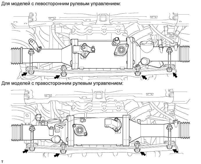
Для моделей с левосторонним рулевым управлением:
Подсоедините 5 разъемов и 3 фиксатора.
Для моделей с правосторонним рулевым управлением:
Подсоедините 5 разъемов и 5 фиксаторов.
| 45. INSTALL POWER STEERING LINK ASSEMBLY (w/o VGRS) |
Установите тягу рулевого управления с усилителем и кронштейн кожуха рейки на переднюю раму и закрепите их 4 болтами и 4 гайками.
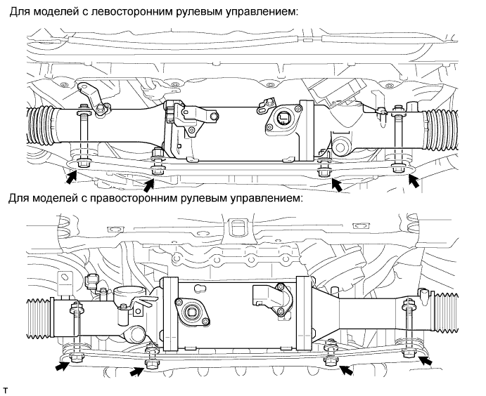
Для моделей с левосторонним рулевым управлением:
Подсоедините 3 разъема и закрепите 3 фиксатора.
Для моделей с правосторонним рулевым управлением:
Подсоедините 3 разъема и закрепите 2 фиксатора.
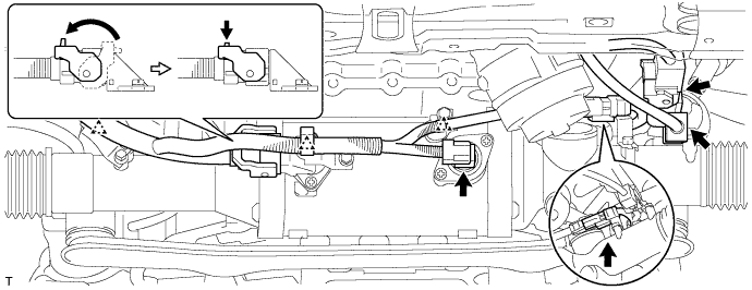
| 46. INSTALL NO. 2 STEERING INTERMEDIATE SHAFT ASSEMBLY (w/ VGRS) |
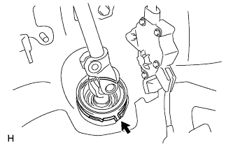 |
Установите зажим на чехол выходного отверстия рулевой колонки.
 |
Совместите метки на промежуточном вале рулевого управления № 2 в сборе и рулевой колонке.
Вверните болт.
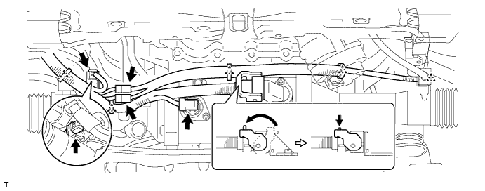
| 47. INSTALL NO. 2 STEERING INTERMEDIATE SHAFT ASSEMBLY (w/o VGRS) |
|
Установите зажим на чехол выходного отверстия рулевой колонки.
|
Совместите метки на промежуточном вале рулевого управления № 2 в сборе и главном вале рулевого управления.
Вверните болт.
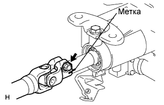
| 48. INSTALL STEERING SLIDING YOKE WITH SHAFT SUB-ASSEMBLY (w/ VGRS) |
 |
Совместите метки на промежуточном вале рулевого управления № 2 в сборе и шлицевом хомуте рулевого вала в сборе.
Совместите метки на шлицевом хомуте рулевого вала в сборе и тяге рулевого управления.
Не затягивая, вверните болт (B).
 |
Вверните болт (A) и затяните болт (B).
| 49. INSTALL STEERING SLIDING YOKE WITH SHAFT SUB-ASSEMBLY (w/o VGRS) |
|
Совместите метки на промежуточном вале рулевого управления № 2 в сборе и шлицевом хомуте рулевого вала в сборе.
Совместите метки на шлицевом хомуте рулевого вала в сборе и промежуточном вале рулевого управления в сборе.
Не затягивая, вверните болт (B).
|
Вверните болт (A) и затяните болт (B).
| 50. INSTALL FRONT SUSPENSION MEMBER REINFORCEMENT LH |
 |
Установите левое усиление элемента передней подвески на автомобиль и закрепите его 4 болтами.
| 51. INSTALL FRONT SUSPENSION MEMBER REINFORCEMENT RH |
| 52. INSTALL FRONT STABILIZER BAR |
Install the stabilizer bar (see page Нажмите здесь).
| 53. INSTALL PROPELLER WITH CENTER BEARING SHAFT ASSEMBLY |
Install the propeller shaft (see page Нажмите здесь).
| 54. INSTALL NO. 1 EXHAUST PIPE SUPPORT BRACKET SUB-ASSEMBLY |
 |
Install the bracket with the 2 bolts.
| 55. INSTALL FRONT EXHAUST PIPE ASSEMBLY |
Install the front exhaust pipe (see page Нажмите здесь).
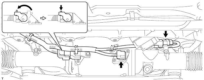
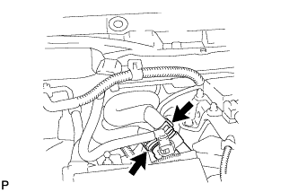
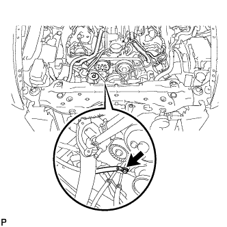
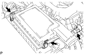
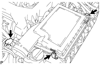
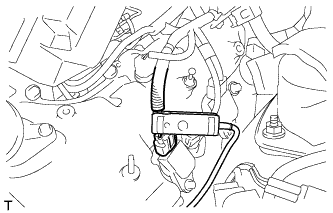
| 56. CONNECT HOSES AND CONNECTORS |
 |
Connect the purge line hose.
 |
Connect the 2 heater hoses.
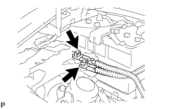 |
Connect the wires with No. 1 engine room junction block with the 2 nuts.
 |
Connect the ground wire with the bolt.
 |
Connect the 3 connectors with front controller with the clamp.
 |
Attach the clamp and connect the cooler compressor connector.
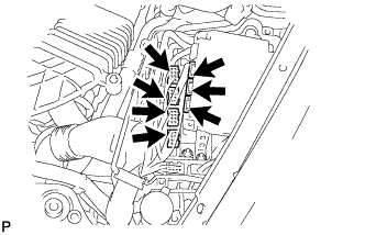 |
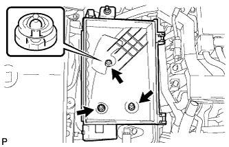
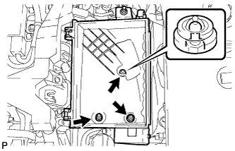
Connect the 3 ECT connectors and 4 ECM connectors.
Install the ECM box cover (upper).
| 57. CONNECT NO. 3 FUEL HOSE |
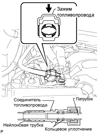 |
Push in the tube connector to the pipe until the tube connector makes a "click" sound.
Install the fuel pipe clamp.
| 58. INSTALL ENGINE ROOM ECU OUTLET DUCT |
 |
Install the outlet duct.
| 59. CONNECT NO. 2 RADIATOR HOSE |
| 60. CONNECT NO. 1 RADIATOR HOSE |
| 61. INSTALL AIR CLEANER ASSEMBLY RH |
 |
Install the air cleaner case with the 2 nuts and clip.
Install the air cleaner element to the air cleaner case.
 |
Install the air cleaner cap with the 2 clamps.
Connect the MAF meter connector.
| 62. INSTALL AIR CLEANER ASSEMBLY LH |
 |
Install the air cleaner case with the 2 nuts and clip.
Install the air cleaner element to the air cleaner case.
 |
Install the air cleaner cap with the 2 clamps.
Connect the MAF meter connector.
| 63. INSTALL V-RIBBED BELT |
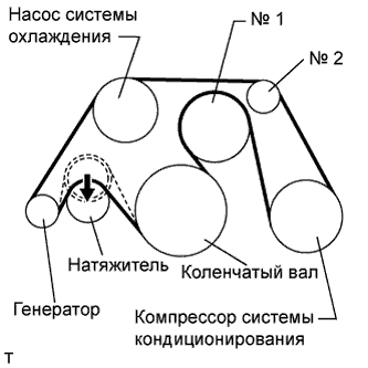 |
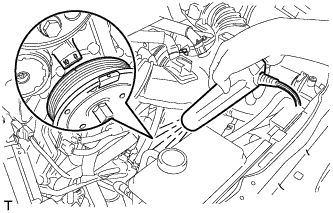
Install the V belt as shown in the illustration.
Rotate the tensioner pulley counterclockwise, and then remove the fix bar.
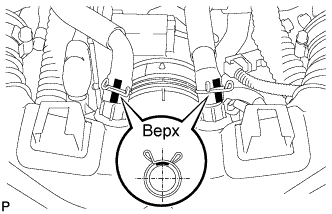
| 64. INSTALL INTAKE AIR CONNECTOR PIPE |
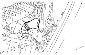
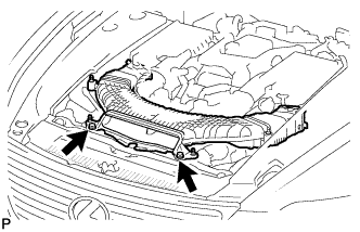
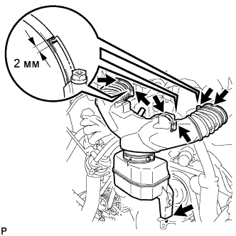 |
Align the protrusion of the intake air resonator with the cutout of the bracket and insert the protrusion.
Install the intake air connector pipe with the 3 hose clamps.
 |
Connect the No. 1 ventilation hose and No. 2 ventilation hose to the intake air connector pipe.
| 65. INSTALL NO. 1 AIR CLEANER INLET |
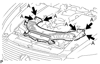 |
Align the holes with the connection areas labeled A, and attach the No. 1 air cleaner inlet.
 |
Install the No. 1 air cleaner inlet with the 2 bolts.
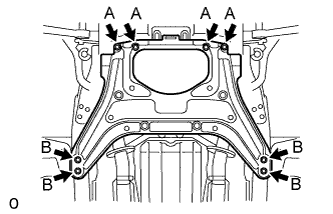
| 66. INSTALL FRONT SUSPENSION CROSSMEMBER LOWER |
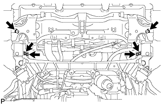 |
Install the suspension crossmember lower with the 6 bolts and 4 nuts.
| 67. INSTALL FRONT BUMPER COVER |
Install the front bumper cover (see page Нажмите здесь).
| 68. CONNECT NO. 1 OIL COOLER OUTLET HOSE |
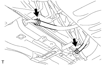 |
Using needle-nose pliers, grip the claws of the clip and slide the clip to connect the oil cooler hose.
| 69. CONNECT NO. 1 OIL COOLER INLET HOSE |
Using needle-nose pliers, grip the claws of the clip and slide the clip to connect the oil cooler hose.
| 70. ADD ENGINE OIL |
Add fresh oil.
| Oil grade | Oil Viscosity (SAE) |
| API grade SL or SM multigrade engine oil | - 0W-20 - 5W-20 - 5W-30 - 10W-30 - 15W-40 - 20W-50 (0W-20 is best choice for fuel economy and good starting in cold weather.) |
| Item | Specified Condition |
| Drain and refill with oil filter change | 8.6 liters (9.1 US qts, 7.6 Imp. qts) |
| Drain and refill without oil filter change | 8.4 liters (8.9 US qts, 7.4 Imp. qts) |
| Dry fill | 10.2 liters (10.8 US qts, 9.0 Imp. qts) |
Install the oil filler cap.
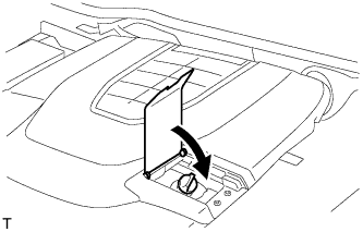 |
Close the oil filler cap service hole cover.
| 71. ADD ENGINE COOLANT |
Tighten the radiator drain cock plug and 2 cylinder block drain cock plugs.
Add TOYOTA Super Long Life Coolant (SLLC) into the radiator reservoir.
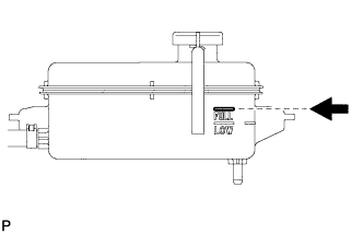 |
Further add coolant into the reservoir until it reaches the FULL line.
Press the No. 1 and No. 2 radiator hoses several times by hand, and then check the coolant level.
If the coolant level is low, add coolant.
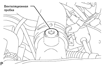 |
Using a 6 mm hexagon wrench, install the vent plug.
Bleed air from the cooling system.
While idling the engine for approximately 10 minutes, make sure the coolant remains at the FULL line by adding coolant as necessary.
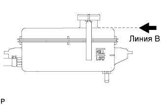 |
After idling the engine for 10 minutes, add coolant until it reaches the B line at the base of the reservoir's filler neck.
Close the radiator reservoir cap, and run the engine at 1500 to 2000 rpm for 5 minutes.
Stop the engine and wait until the coolant cools down to ambient temperature.
|
Check the coolant level.
If the coolant level is below the FULL line, add coolant until it reaches the FULL line.
| 72. CONNECT CABLE TO NEGATIVE BATTERY TERMINAL |
| 73. PERFORM INITIALIZATION |
Perform initialization (see page Нажмите здесь).
| 74. INSPECT FOR OIL LEAK |
Inspect for engine oil leak (see page Нажмите здесь).
| 75. INSPECT FOR COOLANT LEAK |
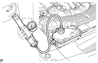 |
Fill the radiator with coolant and attach a radiator cap tester.
Warm up the engine.
Using the radiator cap tester, increase the pressure inside the radiator to 118 kPa (1.2 kgf/cm2, 17 psi), and check that the pressure does not drop.
If the pressure drops, check the hoses, radiator and water pump for leaks. If no external leaks are found, check the heater core, cylinder block and head.
| 76. INSPECT FOR FUEL LEAK |
Connect the intelligent tester to the DLC3.
Turn the engine switch on (IG).
Push the intelligent tester main switch ON.
Select the following menus: Powertrain / Engine / Active Test / Control the Fuel Pump /Speed.
Check the fuel pump operation.
Check for pressure in the fuel inlet tube from the fuel line. Check that the sound of fuel flowing in the fuel tank can be heard.
If no sound can be heard, check the integration relay, fuel pump, ECM and wiring connector.
Check for fuel leaks.
Check that there are no fuel leaks anywhere on the system after performing maintenance.
If there is a fuel leak, repair or replace parts as necessary.
| 77. INSPECT FOR EXHAUST GAS LEAK |
If gas is leaking, tighten the areas necessary to stop the leak. Replace the damaged parts as necessary.
| 78. INSTALL FRONT WHEEL |
| 79. PLACE FRONT WHEELS FACING STRAIGHT AHEAD |
| 80. CHECK AND ADJUST FRONT WHEEL ALIGNMENT |
Check and adjust the front wheel alignment (see page Нажмите здесь).
| 81. CHECK SHIFT LEVER POSITION |
Проверьте положение рычага переключения передач (см. стр. Нажмите здесь).
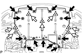
| 82. INSTALL FRONT SUSPENSION MEMBER PROTECTOR LOWER |
 |
Install the suspension member protector with the 8 bolts.
| 83. INSTALL NO. 2 ENGINE UNDER COVER |
 |
Install the under cover with the 8 bolts.
| 84. INSTALL NO. 1 ENGINE UNDER COVER |
 |
Install the cover with the 7 clips and 13 screws.
| 85. CHECK IGNITION TIMING |
Warm up and stop the engine.
When using the intelligent tester:
Connect the intelligent tester to the DLC3.
Start the engine and idle it.
Push the intelligent tester main switch ON.
Enter the following items: Powertrain / Engine and ECT / Data List / Primary / IGN Advance /
When not using the intelligent tester:
Remove the V-bank cover.
Remove the 5 clips and air cleaner inlet cover.
Remove the 4 clips and engine room side cover LH.
Remove the 2 bolts and No. 1 air cleaner inlet.
Disconnect the air cleaner cap. (for Bank 1)
Remove the 2 nuts and air cleaner case. (for Bank 1)
 |
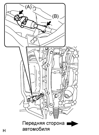
Connect the tester probe of a timing light to the wire of the ignition connector for No. 1 cylinder.
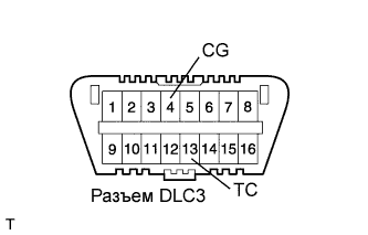 |
Using SST, connect terminals 13 (TC) and 4 (CG) of the DLC3.
 |
Using a timing light, check the ignition timing.
Remove SST from the DLC3.
Check the ignition timing.
Check that the ignition timing advances immediately when the engine speed is increased.
Disconnect the timing light from the engine.
Install the air cleaner case (for Bank 1) with the 2 nuts.
Connect the air cleaner cap. (for Bank 1)
Install the No. 1 air cleaner inlet with the 2 bolts.
Install the engine room side cover LH with the 4 clips.
Install the air cleaner inlet cover with the 5 clips.
Install the V-bank cover.
| 86. CHECK IDLE SPEED |
Warm up and stop the engine.
When using the intelligent tester:
Connect the intelligent tester to the DLC3.
Race the engine speed at 2,500 rpm for approximately 90 seconds.
Push the intelligent tester main switch ON.
Enter the following items: Powertrain / Engine and ECT / Data List / Primary / Engine Speed /
Disconnect the intelligent tester from the DLC3.
When not using the intelligent tester:
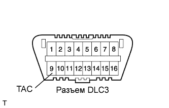 |
Using SST, connect a tachometer probe to terminal 9 (TAC) of the DLC3.
Race the engine speed at 2,500 rpm for approximately 90 seconds.
Check the idle speed.
Disconnect the tachometer from the DLC3.
| 87. CHECK CO/HC |
Start the engine.
Keep the engine speed at 2,500 rpm for approximately 180 seconds.
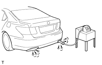 |
Insert the CO / HC meter testing probe at least 40 cm (1.3 ft) into the tailpipe during idling.
Immediately check CO / HC concentration at idle and 2,500 rpm.
Check the A/F sensor and heated oxygen sensor operation.
See the table below for possible causes, then inspect and correct the applicable causes if necessary.
| CO | HC | Symptom | Causes |
| Normal | High | Rough idle |
|
| Low | High | Rough idle (Fluctuating HC reading) |
|
| High | High | Rough idle (Black smoke from exhaust) |
|
| 88. CHECK ENGINE OIL LEVEL |
Warm up the engine, stop the engine and wait 5 minutes. The oil level should be between the dipstick's low level mark and full level mark.
If low, check for leakage and add oil up to the full level mark.
| 89. INSTALL ENGINE ROOM SIDE COVER RH |
 |
Install the side cover with the 4 clips.
| 90. INSTALL ENGINE ROOM SIDE COVER LH |
 |
Install the side cover with the 4 clips.
| 91. INSTALL AIR CLEANER INLET COVER SUB-ASSEMBLY |
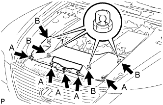 |
Attach the 4 clips B.
Install the air cleaner inlet cover with the 5 clips A.
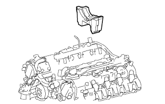
| 92. INSTALL V-BANK COVER SUB-ASSEMBLY |
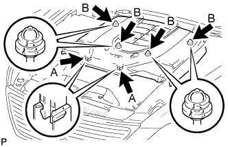 |
After sliding the cover from the vehicle front to the rear to attaching the 2 clips A, attach the 4 clips B and install the V bank cover.
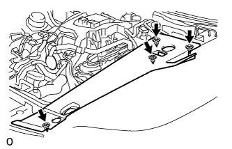
| 93. INSTALL COWL TOP VENTILATOR LOUVER RH |
 |
Install the 6 clips and cowl top ventilator louver RH.
