ДВИГАТЕЛЬ > СНЯТИЕ |
| 1. PLACE FRONT WHEELS FACING STRAIGHT AHEAD |
| 2. DISCHARGE FUEL SYSTEM PRESSURE |
Discharge fuel system pressure (see page Нажмите здесь).
| 3. REMOVE COWL TOP VENTILATOR LOUVER RH |
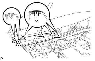 |
Remove the 6 clips and cowl top ventilator louver RH.
| 4. DISCONNECT CABLE FROM NEGATIVE BATTERY TERMINAL |
| 5. REMOVE V-BANK COVER SUB-ASSEMBLY |
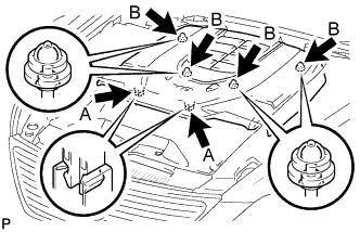 |
While using both hands, lift the rear side of the cover upwards to detach the 4 clips B. Slide the cover towards the front of the vehicle to detach the 2 clips labeled A, and remove the V-bank cover.
| 6. REMOVE AIR CLEANER INLET COVER SUB-ASSEMBLY |
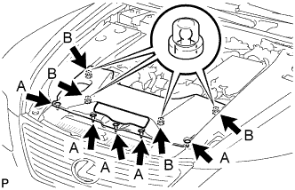 |
Remove the 5 clips A.
Lift up the air cleaner inlet cover to detach the 4 clips B, and remove the cover.
| 7. REMOVE ENGINE ROOM SIDE COVER RH |
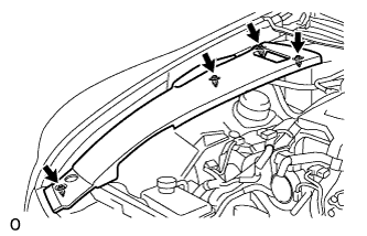 |
Remove the 4 clips and engine room side cover.
| 8. REMOVE ENGINE ROOM SIDE COVER LH |
 |
Remove the 4 clips and engine room side cover.
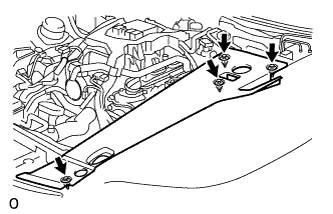
| 9. REMOVE NO. 1 ENGINE UNDER COVER |
 |
Remove the 13 screws, 7 clips and cover.
| 10. REMOVE NO. 2 ENGINE UNDER COVER |
 |
Remove the 8 bolts and under cover.
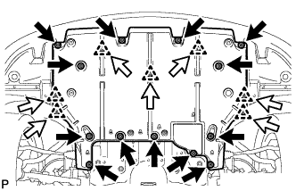
| 11. REMOVE FRONT SUSPENSION MEMBER PROTECTOR LOWER |
 |
Remove the 8 bolts and suspension member protector.
| 12. DRAIN ENGINE OIL |
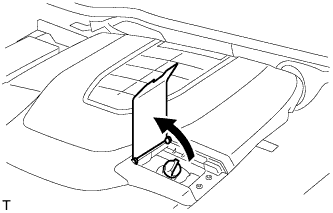 |
Open the oil filler cap service hole cover.
Remove the oil filler cap.
Remove the oil pan drain plug and drain the engine oil into a container.
Install a new gasket and the oil pan drain plug.
| 13. DRAIN ENGINE COOLANT |
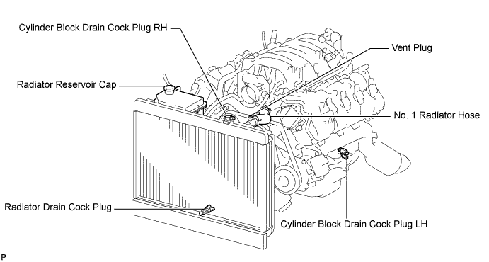
Loosen the radiator drain cock plug.
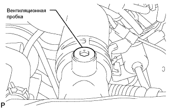 |
Remove the radiator reservoir cap, and using a 6 mm hexagon wrench, remove the vent plug.
Drain coolant.
Loosen the 2 cylinder block drain cock plugs.
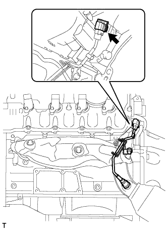
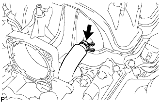
| 14. DISCONNECT NO. 1 OIL COOLER INLET HOSE |
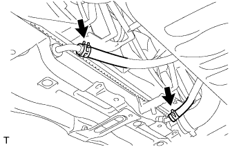 |
Using needle-nose pliers, grip the claws of the clip and slide the clip to disconnect the oil cooler hose.
| 15. DISCONNECT NO. 1 OIL COOLER OUTLET HOSE |
Using needle-nose pliers, grip the claws of the clip and slide the clip to disconnect the oil cooler hose.
| 16. REMOVE FRONT WHEEL |
| 17. REMOVE FRONT BUMPER COVER |
Remove the front bumper cover (see page Нажмите здесь).
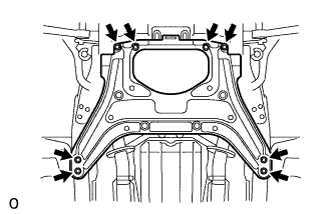
| 18. REMOVE FRONT SUSPENSION CROSSMEMBER LOWER |
 |
Remove the 6 bolts, 4 nuts and suspension crossmember lower.
| 19. REMOVE NO. 1 AIR CLEANER INLET |
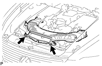 |
Remove the 2 bolts.
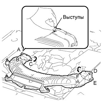 |
Hold the air cleaner inlet by the protrusions A and B, and detach the connections.
Rotate the No. 1 air cleaner inlet as shown in the illustration to detach the protrusion C.
Hold the air cleaner inlet by the protrusions D and E, and detach the connections.
Rotate the No. 1 air cleaner inlet as shown in the illustration to detach the protrusion F.
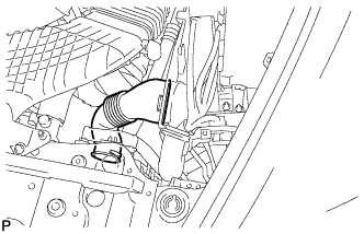
| 20. REMOVE INTAKE AIR CONNECTOR PIPE |
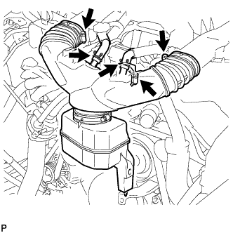 |
Disconnect the No. 1 ventilation hose and No. 2 ventilation hose from the intake air connector pipe.
Loosen the 3 hose clamps, and remove the intake air connector pipe.
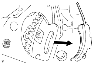
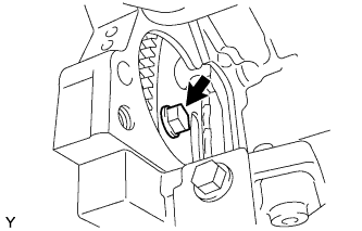
| 21. REMOVE V-RIBBED BELT |
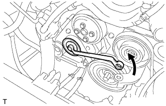 |
Rotate the tensioner pulley counterclockwise to loosen the belt tension.
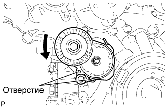 |
While turning the belt tensioner counterclockwise, align the holes. Insert a bar of φ5 mm (0.20 in.) into the holes to fix the belt tensioner in place.
Remove the V belt.
| 22. REMOVE AIR CLEANER ASSEMBLY LH |
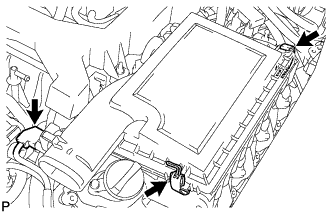 |
Disconnect the MAF meter connector.
Disconnect the 2 clamps and air cleaner cap.
Remove the air cleaner element from air cleaner case.
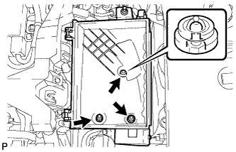 |
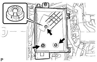
Remove the 2 nuts, clip and air cleaner case.
| 23. REMOVE AIR CLEANER ASSEMBLY RH |
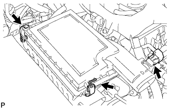 |
Disconnect the MAF meter connector.
Disconnect the 2 clamps and air cleaner cap.
Remove the air cleaner element from air cleaner case.
 |
Remove the 2 nuts, clip and air cleaner case.
| 24. DISCONNECT NO. 1 RADIATOR HOSE |
| 25. DISCONNECT NO. 2 RADIATOR HOSE |
| 26. REMOVE ENGINE ROOM ECU OUTLET DUCT |
 |
Remove the outlet duct.
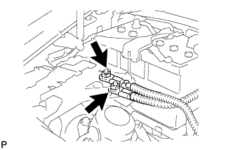
| 27. DISCONNECT NO. 3 FUEL HOSE |
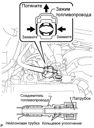 |
Remove the fuel pipe clamp.
Pinch the tube connector and then pull out the fuel hose.
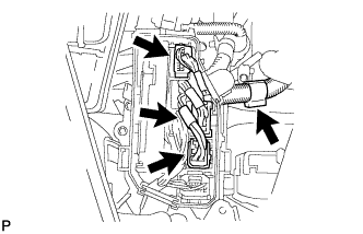
| 28. DISCONNECT HOSES AND CONNECTORS |
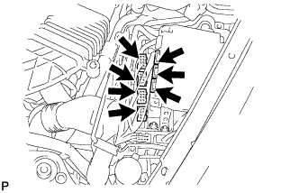 |
Remove the ECM box cover (upper).
Disconnect the 3 ECT connectors and 4 ECM connectors from the ECM box.
 |
Detach the clamp and disconnect the cooler compressor connector.
 |
Detach the clamp and disconnect the 3 connectors with front controller.
 |
Remove the bolt and disconnect the ground wire.
 |
Remove the 2 nuts and disconnect the wires with No. 1 engine room junction block.
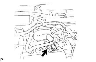 |
Disconnect the 2 heater hoses.
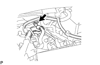 |
Disconnect the purge line hose.
| 29. REMOVE FRONT EXHAUST PIPE ASSEMBLY |
Remove the front exhaust pipe (see page Нажмите здесь).
| 30. REMOVE NO. 1 EXHAUST PIPE SUPPORT BRACKET SUB-ASSEMBLY |
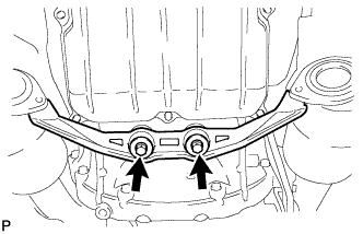 |
Remove the 2 bolts and bracket.
| 31. REMOVE PROPELLER WITH CENTER BEARING SHAFT ASSEMBLY |
Remove the propeller shaft (see page Нажмите здесь).
| 32. REMOVE FRONT STABILIZER BAR |
Remove the front stabilizer bar (see page Нажмите здесь).
| 33. REMOVE FRONT SUSPENSION MEMBER REINFORCEMENT RH |
| 34. REMOVE FRONT SUSPENSION MEMBER REINFORCEMENT LH |
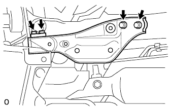 |
Выверните 4 болта и снимите левое усиление элемента передней подвески с автомобиля.
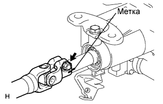
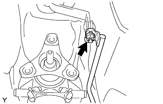
| 35. REMOVE STEERING SLIDING YOKE WITH SHAFT SUB-ASSEMBLY (w/ VGRS) |
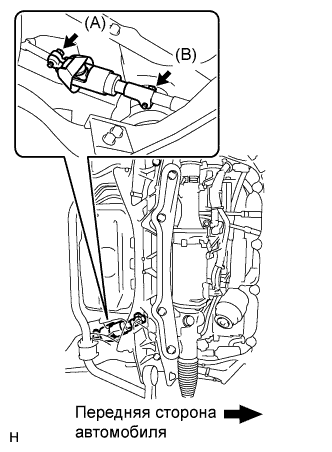 |
Ослабьте болт (A), выверните болт (B), а затем сдвиньте шлицевой хомут рулевого вала вместе с валом.
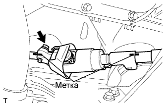 |
Нанесите метки на шлицевой хомут рулевого вала, промежуточный вал № 2 рулевого управления и тягу рулевого управления.
Выверните болт и снимите шлицевой хомут рулевого вала с промежуточного вала № 2 рулевого управления.
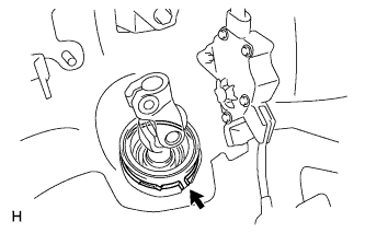
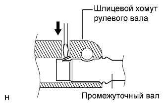 |
Отсоедините вал шлицевого хомута от тяги рулевого управления.
| 36. REMOVE STEERING SLIDING YOKE WITH SHAFT SUB-ASSEMBLY (w/o VGRS) |
|
Ослабьте болт (A), выверните болт (B), а затем сдвиньте шлицевой хомут рулевого вала.
|
Нанесите метки на шлицевой хомут рулевого вала, промежуточный вал № 2 рулевого управления и тягу рулевого управления.
Выверните болт и снимите шлицевой хомут рулевого вала с промежуточного вала № 2 рулевого управления.
|
Отсоедините шлицевой хомут рулевого вала от промежуточного вала рулевого управления.
| 37. REMOVE NO. 2 STEERING INTERMEDIATE SHAFT ASSEMBLY (w/ VGRS) |
 |
Нанесите метки на промежуточный вал № 2 рулевого управления и рулевую колонку.
Выверните болт.
 |
Снимите зажим и промежуточный вал № 2 рулевого управления.
| 38. REMOVE NO. 2 STEERING INTERMEDIATE SHAFT ASSEMBLY (w/o VGRS) |
|
Нанесите метки на промежуточный вал № 2 рулевого управления и рулевую колонку.
Выверните болт.
|
Снимите зажим и промежуточный вал № 2 рулевого управления.
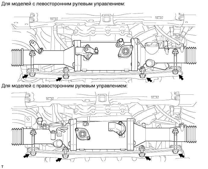
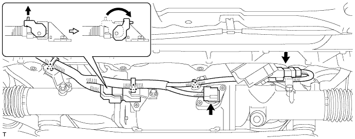
| 39. REMOVE POWER STEERING LINK ASSEMBLY (w/ VGRS) |
Для моделей с левосторонним рулевым управлением:
Расцепите 3 фиксатора и отсоедините 5 разъемов.
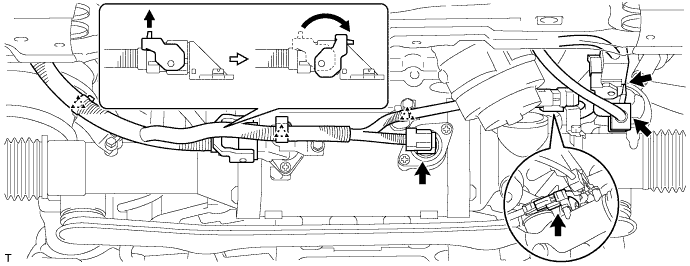
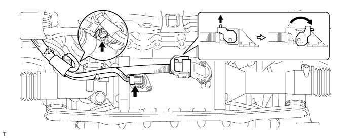
Для моделей с правосторонним рулевым управлением:
Расцепите 5 фиксаторов и отсоедините 5 разъемов.
Выверните 4 болта, отверните 4 гайки и снимите тягу рулевого управления с усилителем с передней рамы и кронштейна кожуха рейки.
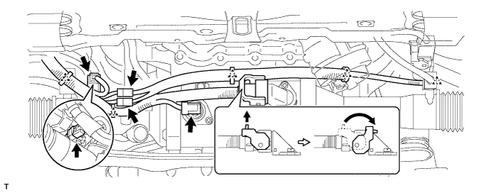
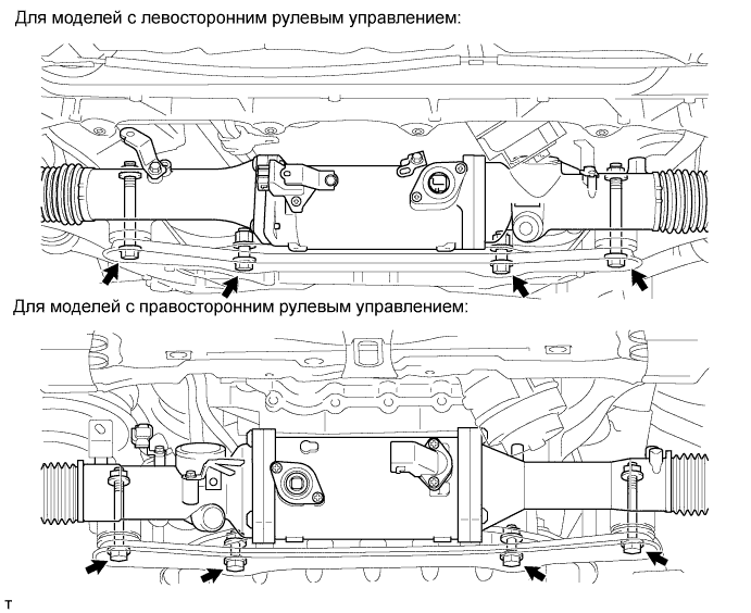
| 40. REMOVE POWER STEERING LINK ASSEMBLY (w/o VGRS) |
Для моделей с левосторонним рулевым управлением:
Расцепите 3 фиксатора и отсоедините 3 разъема.
Для моделей с правосторонним рулевым управлением:
Расцепите 2 фиксатора и отсоедините 3 разъема.
Выверните 4 болта, отверните 4 гайки и снимите тягу рулевого управления с усилителем с передней рамы и кронштейна кожуха рейки.
| 41. REMOVE NO. 2 EXHAUST MANIFOLD HEAT INSULATOR |
 |
Disconnect the sensor connector.
 |
Remove the 3 bolts and heat insulator.
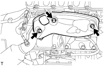
| 42. REMOVE EXHAUST MANIFOLD SUB-ASSEMBLY (for Bank 1) |
 |
Remove the 8 nuts, exhaust manifold and gasket.
| 43. DISCONNECT COOLER COMPRESSOR ASSEMBLY |
 |
Remove the 2 bolts, 2 nuts, 2 stud bolts and disconnect the cooler compressor.
| 44. DISCONNECT FRONT NO. 2 LOWER SUSPENSION ARM ASSEMBLY |
Disconnect the front No. 2 lower suspension arm (see page Нажмите здесь).
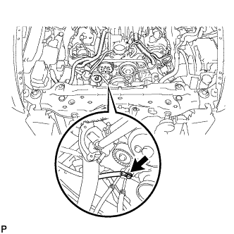
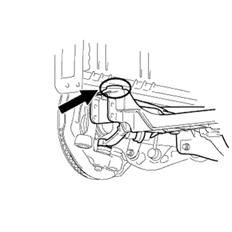
| 45. DISCONNECT FLOOR SHIFT GEAR SHIFTING ROD SUB-ASSEMBLY |
 |
Отверните гайку и отсоедините тягу механизма переключения передач.
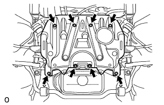
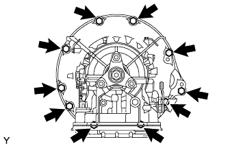
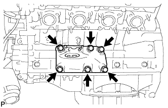
| 46. REMOVE ENGINE AND TRANSMISSION |
 |
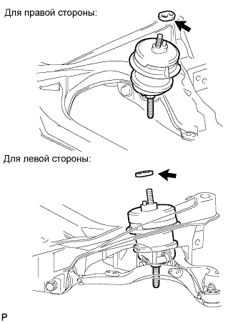
Place a mark (with spray, etc.) over the front right vehicle side attachment area of the crossmember, which is indicated in the illustration.
Place a mark (with spray, etc.) over the front left vehicle side attachment area of the crossmember.
Set an engine lifter underneath the engine.
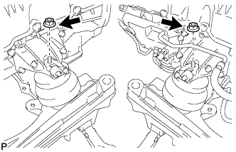
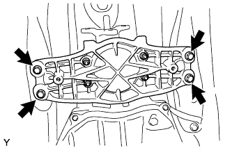 |
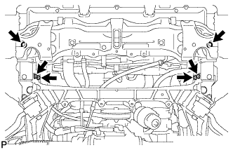
Remove the 4 engine rear mounting member's bolts.
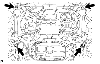 |
Remove the 4 bolts shown in the illustration.
Operate the engine lifter, then slowly remove the engine from the vehicle.
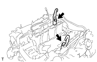 |
Install the 2 engine hangers with the 2 bolts as shown in the illustration.
| Item | Part No. |
| No. 1 engine hanger | 12281-38030 or 12281-38050 |
| Bolt | 90129-14120 |
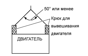 |
Attach an engine sling device and hang the engine with a chain block.
| 47. REMOVE OIL LEVEL DIPSTICK GUIDE |
 |
Remove the dipstick.
Remove the 2 bolts and dipstick guide.
| 48. REMOVE NO. 1 EXHAUST MANIFOLD HEAT INSULATOR |
 |
Disconnect the sensor connector.
 |
Remove the 3 bolts and heat insulator.
| 49. REMOVE EXHAUST MANIFOLD SUB-ASSEMBLY (for Bank 2) |
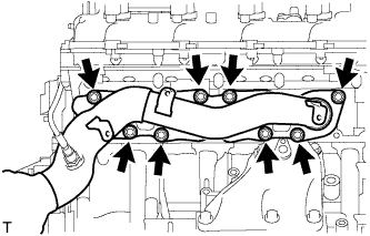 |
Remove the 8 nuts, exhaust manifold and gasket.
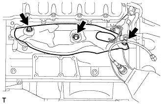
| 50. REMOVE OIL COOLER TUBE |
Выверните 2 болта и снимите 2 зажима.
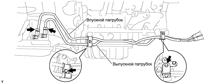
Ослабьте гайки штуцеров впускного и выпускного патрубков масляного радиатора и отсоедините патрубки.
| 51. REMOVE NO. 3 EXHAUST MANIFOLD HEAT INSULATOR |
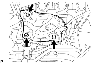 |
Remove the 3 bolts and No. 3 exhaust manifold heat insulator.
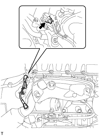
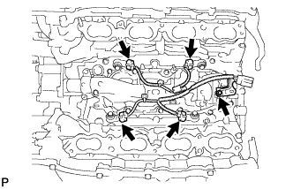
| 52. REMOVE ENGINE WIRE |
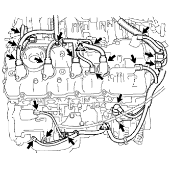
for Engine LH Side:
 |
Disconnect the camshaft timing control valve connector.
Disconnect the 4 ignition coil connectors.
Disconnect the 2 VVT sensor connectors.
Disconnect the No. 8 engine wire connector.
Remove the 2 bolts and disconnect the clamp and 2 clamp brackets.
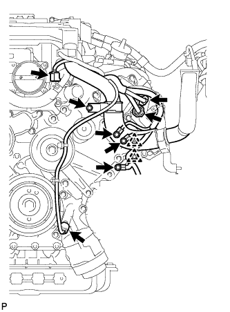 |
Disconnect the engine coolant temperature sensor connector.
Disconnect the oil pressure sensor connector.
Disconnect the 2 camshaft timing control motor connectors. (for Bank 1)
Remove the 3 bolts and disconnect the 3 clamps and ground wire.
Remove the bolt and clamp bracket.
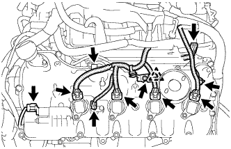
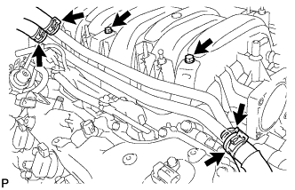
for Engine RH Side:
 |
Disconnect the camshaft timing control valve connector.
Disconnect the 4 ignition coil connectors.
Disconnect the 2 VVT sensor connectors.
Disconnect the engine wire connector.
Disconnect the 2 camshaft timing control motor connectors. (for Bank 2)
Disconnect the camshaft position sensor connector.
Remove the nut and disconnect the generator wire and connector.
Remove the nut and disconnect the starter wire and connector.
Disconnect the crankshaft position sensor connector.
Disconnect the engine oil level sensor connector.
Remove the 3 bolts, and disconnect the 3 clamp brackets and 2 clamps.
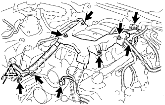 |
Disconnect the throttle body connector.
Disconnect the No. 1 vacuum switching valve connector.
Disconnect the intake air control valve actuator connector.
Remove the 2 bolts and disconnect the 2 clamp brackets and clamp.
Remove the 4 nuts and engine wire.
| 53. REMOVE STARTER ASSEMBLY |
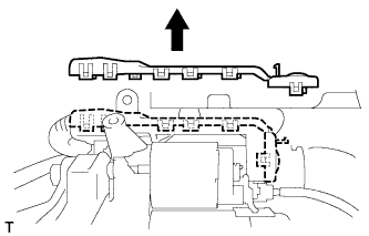 |
Detach the 11 claws and remove the starter terminal upper cover.
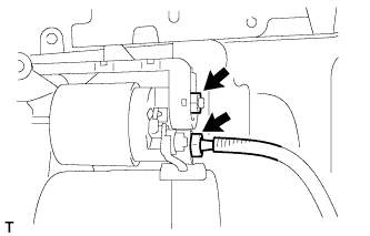 |
Disconnect the starter connector.
Remove the nut and disconnect the wire harness.
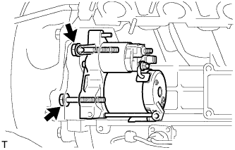 |
Remove the 2 bolts and starter.
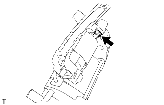 |
Remove the nut and starter terminal lower cover.
 |
Remove the flywheel housing side cover.
| 54. REMOVE AUTOMATIC TRANSMISSION ASSEMBLY |
 |
Снимите боковую крышку картера маховика.
 |
Поверните коленчатый вал, чтобы получить доступ к каждому из болтов.
Зафиксируйте гайку шкива коленчатого вала гаечным ключом и выверните 6 болтов.
 |
Выверните 10 болтов.
Отсоедините и снимите автоматическую трансмиссию.
| 55. REMOVE DRIVE PLATE AND RING GEAR SUB-ASSEMBLY |
 |
Using SST, hold the crankshaft.
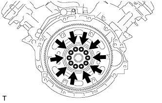 |
Remove the 10 bolts, spacer plate, ring gear and sensor rotor.
| 56. REMOVE FRONT SUSPENSION CROSSMEMBER SUB-ASSEMBLY |
 |
Remove the 2 nuts, then remove the crossmember from the engine.
| 57. REMOVE ENGINE MOUNTING SPACER |
 |
Remove the 2 mounting spacers.
| 58. INSTALL ENGINE ON ENGINE STAND |
Install the engine onto an engine stand with the bolts.
Remove the 2 bolts and 2 engine hangers.
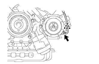
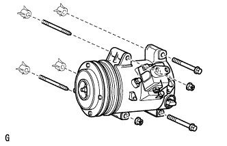
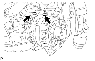
| 59. REMOVE GENERATOR ASSEMBLY |
 |
Remove the nut, and disconnect the harness from the +B terminal.
Disconnect the generator connector.
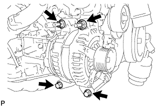 |
Remove the 2 bolts and 2 nuts.
 |
Using an E8 "TORX" socket wrench, remove the 2 stud bolts and generator.
| 60. REMOVE ENGINE MOUNTING DAMPER |
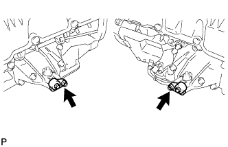 |
Remove the 2 nuts and 2 mounting dampers.
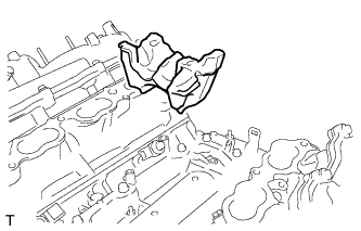
| 61. REMOVE FRONT NO. 1 ENGINE MOUNTING BRACKET RH |
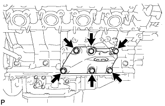 |
Remove the 6 bolts and mounting bracket.
| 62. REMOVE FRONT NO. 1 ENGINE MOUNTING BRACKET LH |
 |
Remove the 6 bolts and mounting bracket.
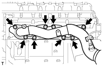
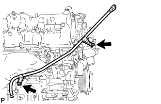
| 63. REMOVE WATER BY-PASS PIPE SUB-ASSEMBLY |
 |
Slide the 4 clamps, and disconnect the heater water inlet hose, heater water outlet hose, water inlet hose, and No. 3 water by-pass hose from the water by-pass pipe sub-assembly.
Remove the 2 bolts and water by-pass pipe.
| 64. REMOVE VENTILATION HOSE |
| 65. REMOVE THROTTLE BODY ASSEMBLY |
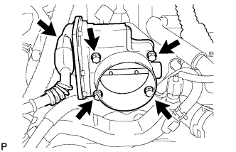 |
Disconnect the throttle motor connector.
Remove the 4 bolts and throttle body.
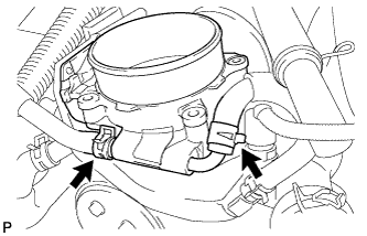 |
Slide the clamps, and disconnect the No. 4 and No. 5 water by-pass hoses from the throttle body.
Remove the gasket from the intake manifold.
| 66. REMOVE INTAKE MANIFOLD |
 |
Disconnect the No. 1 ventilation hose from the intake manifold.
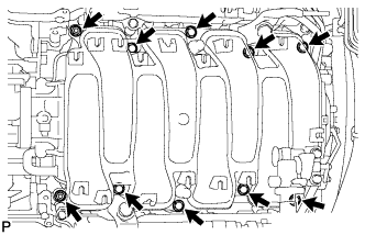 |
Remove the 8 bolts, 2 nuts and intake manifold.
Remove the 2 gaskets from the intake manifold.
| 67. REMOVE NO. 3 ENGINE COVER |
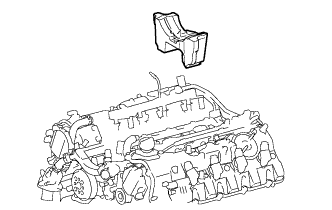 |
Remove the No. 3 engine cover.
| 68. REMOVE NO. 2 ENGINE COVER SUB-ASSEMBLY LH |
 |
Remove the No. 2 engine cover sub-assembly LH .
| 69. REMOVE FUEL TUBE SUB-ASSEMBLY |
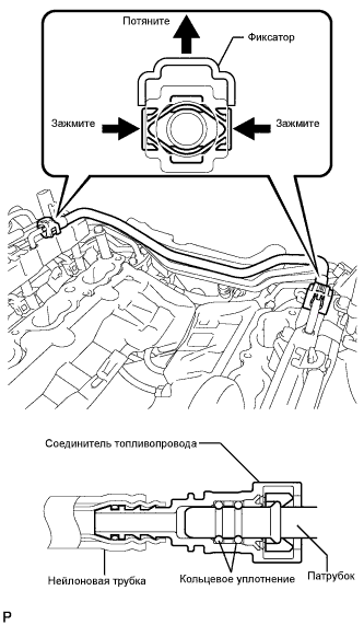 |
Lift up the retainer to release its lock.
Pinch the tube connector and then pull out the fuel tube.
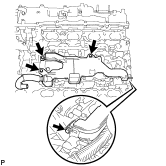
| 70. REMOVE FUEL DELIVERY PIPE |
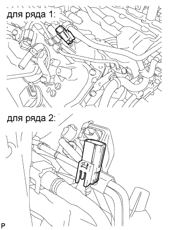 |
Disconnect the 2 connectors.
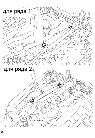 |
Disconnect the 4 wire harness clamps.
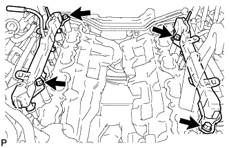 |
Remove the 4 bolts and 2 fuel delivery pipes.
Remove the 4 delivery pipe spacers and 8 insulators from the intake manifold.
| 71. REMOVE FUEL INJECTOR ASSEMBLY |
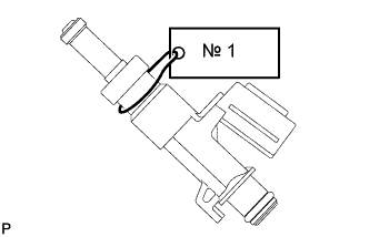 |
Remove the fuel injector from the fuel delivery pipe.
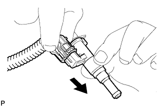 |
Disconnect the connector from the injector.
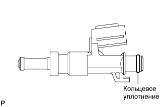 |
Remove the O-ring from the fuel injector assembly.
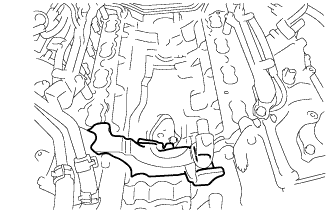
| 72. REMOVE SEPARATOR CASE |
 |
Remove the 4 bolts and case separator.
| 73. REMOVE ENGINE WIRE |
 |
Disconnect the 4 knock sensor connectors.
Remove the bolt and engine wire.
| 74. REMOVE NO. 4 ENGINE COVER SUB-ASSEMBLY |
 |
Remove the engine cover.
| 75. REMOVE NO. 2 IDLER PULLEY SUB-ASSEMBLY |
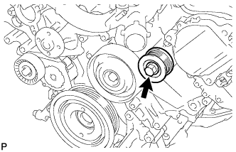 |
Remove the bolt and idler pulley.
| 76. REMOVE NO. 1 IDLER PULLEY SUB-ASSEMBLY |
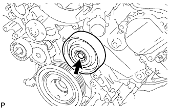 |
Remove the bolt and idler pulley.
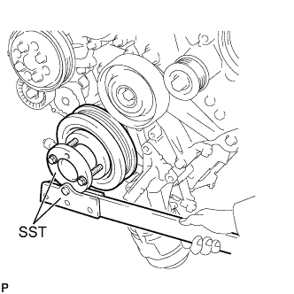
| 77. REMOVE WATER PUMP PULLEY |
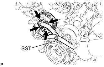 |
Using SST, hold the water pump pulley.
Remove the 4 bolts and water pump pulley.
| 78. REMOVE WATER INLET HOUSING |
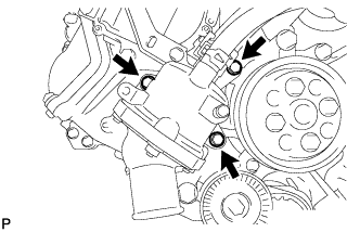 |
Remove the 3 bolts, water inlet housing and gasket.
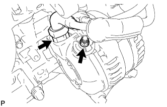
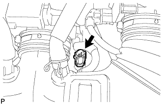
| 79. REMOVE ENGINE OIL PRESSURE SWITCH ASSEMBLY |
Disconnect the switch connector.
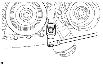 |
Using a 24 mm deep socket wrench, remove the switch.
| 80. REMOVE ENGINE OIL LEVEL SENSOR |
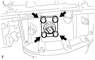 |
Remove the 4 bolts and oil level sensor.
| 81. REMOVE ENGINE COOLANT TEMPERATURE SENSOR |
 |
Disconnect the engine coolant temperature sensor connector.
Remove the engine coolant temperature sensor.
Remove the gasket from the engine coolant temperature sensor.
| 82. REMOVE KNOCK SENSOR |
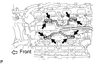 |
Disconnect the 4 knock sensor connectors.
Remove the 4 bolts and 4 knock sensors.
| 83. REMOVE IGNITION COIL |
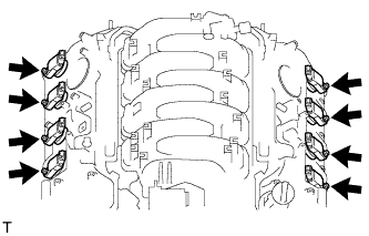 |
Disconnect the 8 ignition coil connectors.
Remove the 8 bolts.
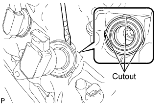 |
Using a screwdriver, pry at the cutouts to remove the 8 ignition coils together with the 8 spark plug tube gaskets.
