БЛОК ДВИГАТЕЛЯ > РАЗБОРКА |
| 1. REMOVE OIL FILLER CAP SUB-ASSEMBLY |
| 2. REMOVE OIL FILLER CAP HOUSING |
 |
Remove the 2 bolts, filler cap housing and gasket.
| 3. REMOVE SPARK PLUG |
 |
Using a 16 mm plug wrench, remove the 8 spark plugs.
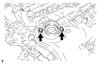
| 4. REMOVE VVT SENSOR |
 |
for Bank 1:
Remove the 2 bolts and 2 VVT sensors.
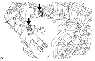 |
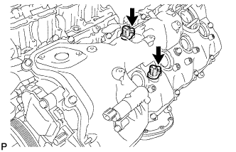
for Bank 2:
Remove the 2 bolts and 2 VVT sensors.
| 5. REMOVE CAMSHAFT POSITION SENSOR |
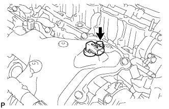 |
Remove the bolt and camshaft position sensor.
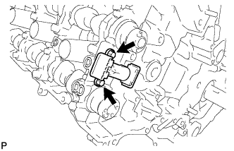
| 6. REMOVE CRANKSHAFT POSITION SENSOR |
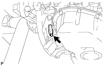 |
Remove the bolt and crankshaft position sensor.
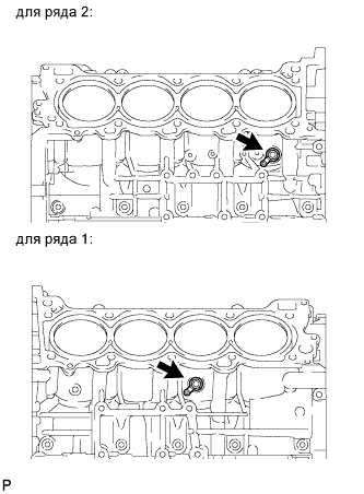
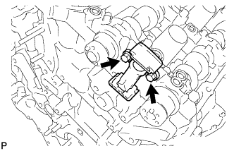
| 7. REMOVE CAMSHAFT TIMING OIL CONTROL VALVE ASSEMBLY |
 |
for Bank 1:
Remove the bolt and oil control valve.
 |
for Bank 2:
Remove the bolt and oil control valve.
| 8. REMOVE CYLINDER BLOCK WATER DRAIN COCK SUB-ASSEMBLY |
 |
Remove the 2 water drain cock plugs from the water drain cocks.
Remove the 2 water drain cocks from the cylinder block.
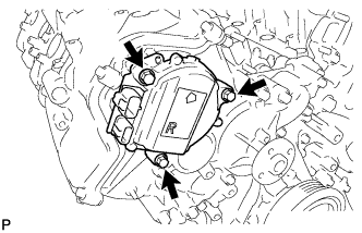
| 9. REMOVE CAMSHAFT TIMING CONTROL MOTOR (for Bank 1) |
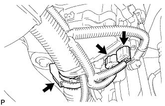 |
Disconnect the 2 camshaft timing control motor connectors and engine wire clamp.
 |
Remove the 3 bolts and camshaft timing control motor.
Remove the O-ring from the timing chain cover.
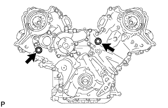
| 10. REMOVE CAMSHAFT TIMING CONTROL MOTOR (for Bank 2) |
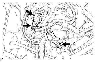 |
Disconnect the 2 camshaft timing control motor connectors.
Remove the bolt and engine wire bracket.
 |
Remove the 3 bolts and camshaft timing control motor.
Remove the O-ring from the timing chain cover.
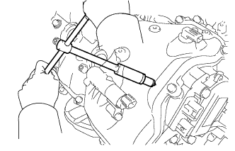
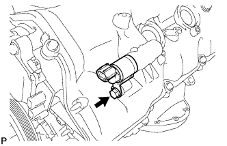
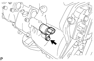
| 11. REMOVE OIL FILTER ELEMENT |
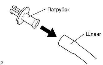 |
Connect a hose with an inside diameter of 15 mm (0.59 in.) to the pipe.
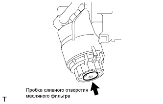 |
Remove the oil filter drain plug.
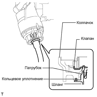 |
Install the pipe to the oil filter cap.
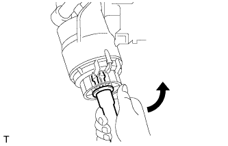 |
Check that oil is drained from the oil filter. Then disconnect the pipe and remove the O-ring, as shown in the illustration.
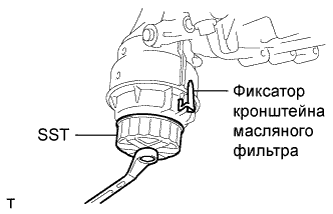 |
Using SST, remove the oil filter cap.
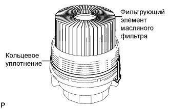 |
Remove the oil filter element and O-ring from the oil filter cap.
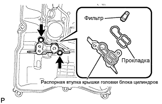
| 12. REMOVE OIL FILTER BRACKET |
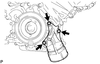 |
Remove the 3 bolts, filter bracket and 2 gaskets.
| 13. REMOVE FRONT WATER BY-PASS JOINT |
 |
Remove the 4 nuts, water by-pass joint and 2 gaskets.
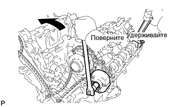
| 14. REMOVE CRANKSHAFT PULLEY |
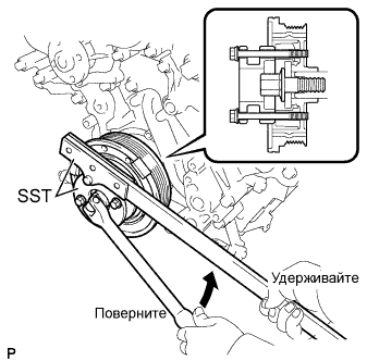 |
Using SST, loosen the crankshaft pulley set bolt.
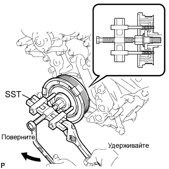 |
Using the pulley set bolt and SST, remove the crankshaft pulley.
| 15. REMOVE SPARK PLUG TUBE GASKET |
 |
Using a screwdriver, pry out the 8 plug tube gaskets.
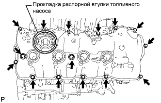
| 16. REMOVE CYLINDER HEAD COVER SUB-ASSEMBLY (for Bank 1) |
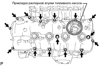 |
Remove the fuel pump spacer gasket.
Remove the 15 bolts, 2 seal washers, cylinder head cover and gasket.
 |
Remove the 4 gaskets and 2 O-rings from the camshaft bearing caps (No. 2, No. 3, No. 7).
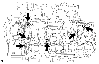
| 17. REMOVE CYLINDER HEAD COVER SUB-ASSEMBLY (for Bank 2) |
 |
Remove the fuel pump spacer gasket.
Remove the 15 bolts, 2 seal washers, cylinder head cover and gasket.
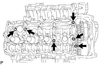 |
Remove the 4 gaskets and 2 O-rings from the camshaft bearing caps (No. 1, No. 3, No. 6).
| 18. REMOVE OIL CONTROL VALVE FILTER |
 |
for Bank 1:
Remove the 2 bolts, cylinder head cover spacer, gasket and valve filter.
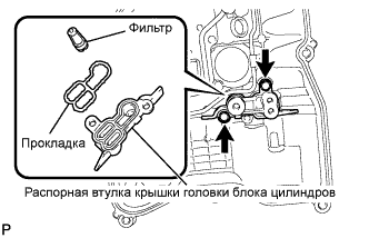 |
for Bank 2:
Remove the 2 bolts, cylinder head cover spacer, gasket and valve filter.
| 19. REMOVE V-RIBBED BELT TENSIONER ASSEMBLY |
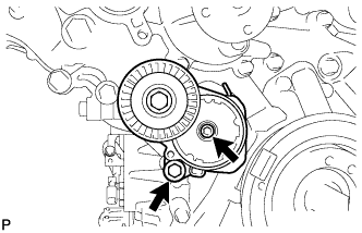 |
Remove the standard bolt, 6 mm hexagon wrench bolt and belt tensioner.
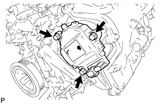
| 20. REMOVE WATER PUMP |
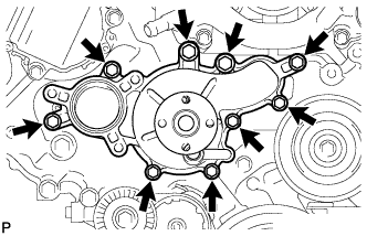 |
Remove the 9 bolts, water pump and gasket.
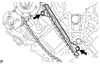
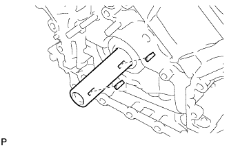
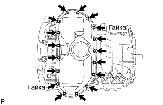
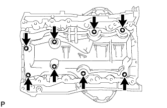
| 21. REMOVE TIMING CHAIN COVER SUB-ASSEMBLY |
 |
Remove the 2 plugs and 2 gaskets.
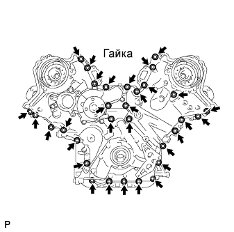 |
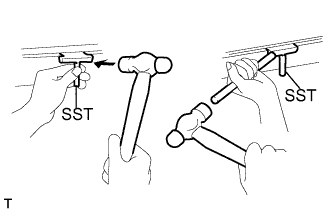
Remove the 30 bolts and nut shown in the illustration.
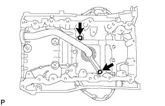
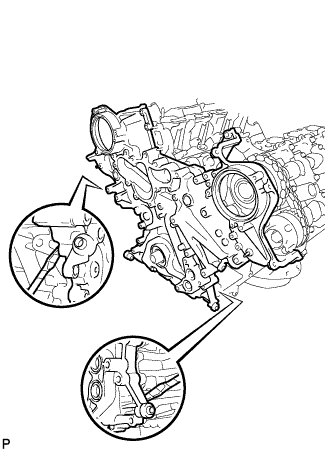 |
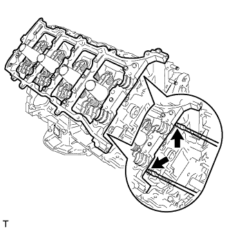
Remove the timing chain cover by prying between the timing chain cover and cylinder head and cylinder block with a screwdriver as shown in the illustration.
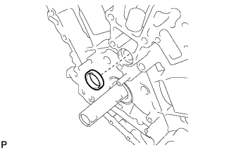 |
Remove the oil pump gasket from the cylinder block.
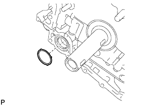 |
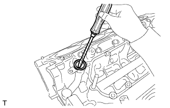
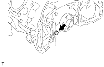
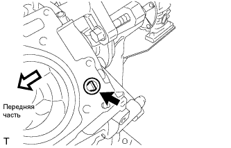
Remove the O-ring from the cylinder block.
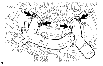
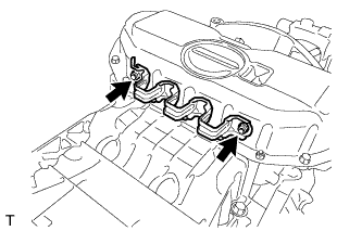
| 22. REMOVE WATER INLET PIPE |
 |
Remove the water inlet pipe.
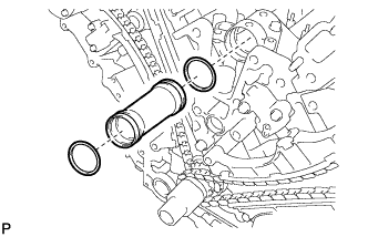
Remove the 2 O-rings from the water inlet pipe.
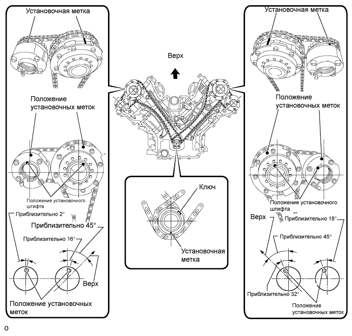
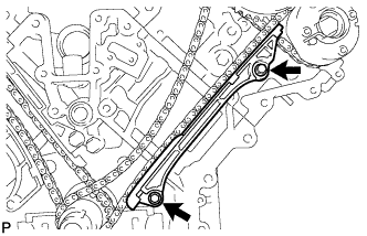
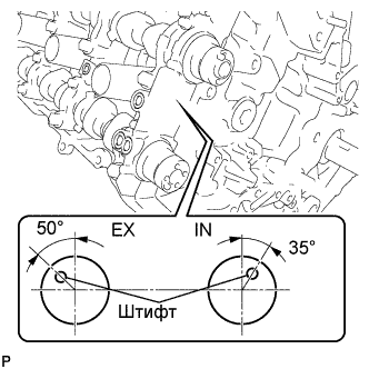
| 23. SET NO. 1 CYLINDER TO TDC / COMPRESSION |
Temporarily tighten the pulley set bolt.
Rotate the crankshaft clockwise so that the timing marks on the crankshaft timing gear and camshaft timing gears are as shown in the illustration.
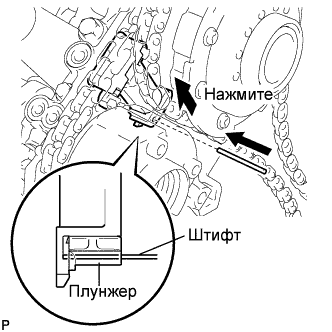
| 24. REMOVE NO. 1 CHAIN TENSIONER ASSEMBLY (for Bank 1) |
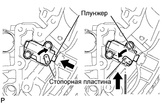 |
Move the stopper plate upward to release the lock, and push the plunger deep into the tensioner.
Move the stopper plate downward to set the lock, and insert a hexagon wrench into the stopper plate hole.
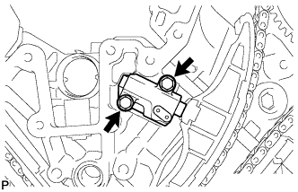 |
Remove the 2 bolts, chain tensioner and gasket.
| 25. REMOVE CHAIN TENSIONER SLIPPER (for Bank 1) |
| 26. REMOVE NO. 1 CHAIN VIBRATION DAMPER (for Bank 1) |
 |
Remove the 2 bolts and chain vibration damper.
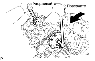
| 27. REMOVE CHAIN SUB-ASSEMBLY (for Bank 1) |
 |
While pushing down the No. 3 chain tensioner, insert a pin of φ1.0 mm (0.039 in.) into the hole to fix it in place.
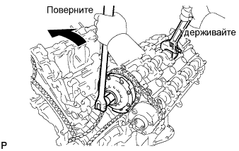 |
Hold the hexagonal portion of the camshaft with a 12 mm hexagon wrench and loosen the bolt.
 |
Hold the hexagonal portion of the camshaft with a wrench and loosen the bolt.
Remove the 2 bolts. Then with the No. 1 and No. 2 chains still connected to the gears, remove the camshaft timing gear assembly, camshaft timing exhaust gear assembly and crankshaft timing sprocket.
Remove the No. 1 and No. 2 chains from the gears.
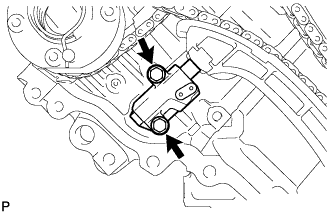
| 28. REMOVE NO. 3 CHAIN TENSIONER ASSEMBLY |
 |
Remove the 2 bolts and chain tensioner.
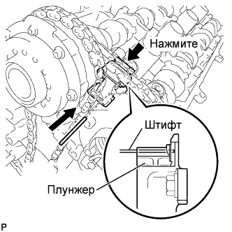
| 29. REMOVE NO. 1 CHAIN TENSIONER ASSEMBLY (for Bank 2) |
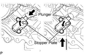 |
Move the stopper plate upward to release the lock, and push the plunger deep into the tensioner.
Move the stopper plate downward to set the lock, and insert a hexagon wrench into the stopper plate hole.
 |
Remove the 2 bolts and chain tensioner.
| 30. REMOVE CHAIN TENSIONER SLIPPER (for Bank 2) |
| 31. REMOVE NO. 1 CHAIN VIBRATION DAMPER (for Bank 2) |
 |
Remove the 2 bolts and vibration damper.
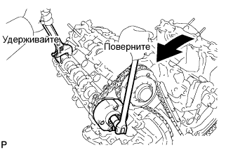
| 32. REMOVE CHAIN SUB-ASSEMBLY (for Bank 2) |
 |
While raising up the No. 2 chain tensioner, insert a pin of φ1.0 mm (0.039 in.) into the hole to fix it in place.
 |
Hold the hexagonal portion of the camshaft with a 12 mm hexagon wrench and loosen the bolt.
 |
Hold the hexagonal portion of the camshaft with a wrench and loosen the bolt.
Remove the 2 bolts. Then with the No. 1 and No. 2 chains still connected to the gears, remove the camshaft timing gear assembly, camshaft timing exhaust gear assembly and crankshaft timing sprocket.
Remove the No. 1 and No. 2 chains from the gears.
| 33. REMOVE NO. 2 CHAIN TENSIONER ASSEMBLY |
 |
Remove the 2 bolts and chain tensioner.
| 34. REMOVE CRANKSHAFT TIMING GEAR KEY |
 |
Using a screwdriver, remove the 2 timing gear keys from the crankshaft.
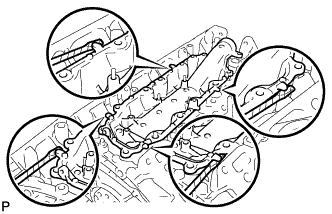
| 35. REMOVE CAMSHAFT BEARING CAP (for Bank 2) |
 |
Make sure that the knock pin of the camshaft is positioned as shown in the illustration.
 |
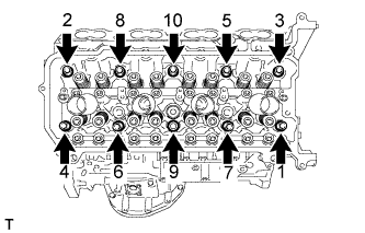
Uniformly loosen and remove the 8 bearing cap bolts in the sequence shown in the illustration.
 |
Uniformly loosen and remove the 18 bearing cap bolts in the sequence shown in the illustration.
Remove the 7 bearing caps.
Remove the No. 1 and No. 2 camshafts.
| 36. REMOVE CAMSHAFT HOUSING SUB-ASSEMBLY (for Bank 2) |
 |
Remove the camshaft housing by prying between the cylinder head and camshaft housing with a screwdriver.
| 37. REMOVE CAMSHAFT BEARING CAP (for Bank 1) |
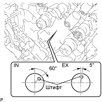 |
Make sure that the knock pin of the camshaft is positioned as shown in the illustration.
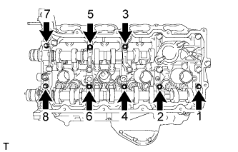 |
Uniformly loosen and remove the 8 bearing cap bolts in the sequence shown in the illustration.
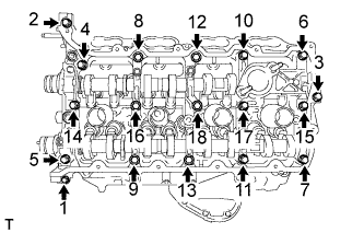 |
Uniformly loosen and remove the 18 bearing cap bolts in the sequence shown in the illustration.
Remove the 7 bearing caps.
Remove the No. 3 and No. 4 camshafts.
| 38. REMOVE CAMSHAFT HOUSING SUB-ASSEMBLY (for Bank 1) |
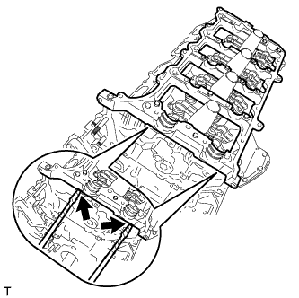 |
Remove the camshaft housing by prying between the cylinder head and camshaft housing with a screwdriver.
| 39. REMOVE NO. 1 VALVE ROCKER ARM SUB-ASSEMBLY |
Remove the 32 valve rocker arms from the cylinder head.
| 40. REMOVE VALVE LASH ADJUSTER ASSEMBLY |
Remove the 32 valve lash adjusters from the cylinder head.
| 41. REMOVE VALVE STEM CAP |
Remove the 32 valve stem caps from the cylinder head.
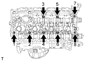
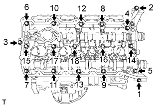
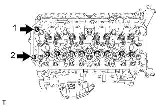
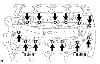
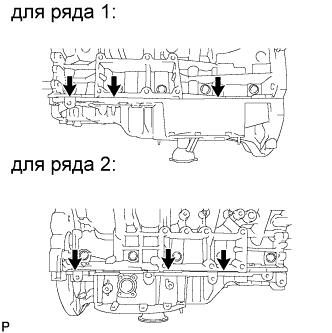
| 42. REMOVE CYLINDER HEAD SUB-ASSEMBLY (for Bank 1) |
 |
Uniformly loosen and remove the 2 bolts in the sequence shown in the illustration.
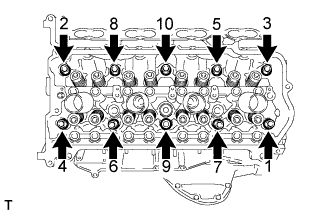 |
Using a 10 mm bi-hexagon wrench, uniformly loosen the 10 bolts in the sequence shown in the illustration. Remove the 10 cylinder head bolts and plate washers.
Remove the cylinder head and gasket.
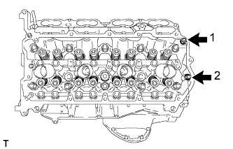
| 43. REMOVE CYLINDER HEAD SUB-ASSEMBLY (for Bank 2) |
 |
Uniformly loosen and remove the 2 bolts in the sequence shown in the illustration.
 |
Using a 10 mm bi-hexagon wrench, uniformly loosen the 10 bolts in the sequence shown in the illustration. Remove the 10 cylinder head bolts and plate washers.
Remove the cylinder head and gasket.
| 44. REMOVE CYLINDER BLOCK WATER JACKET SPACER |
 |
Remove the 2 water jacket spacers from the cylinder head.
| 45. REMOVE OIL RETURN PIPE GASKET |
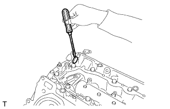 |
Using a screwdriver, pry out the oil return pipe gasket.
| 46. REMOVE NO. 1 HEAT EXCHANGER COVER |
 |
Remove the 11 bolts and 2 nuts.
 |
Remove the heat exchanger by prying between the heat exchanger and cylinder block with a screwdriver.
| 47. REMOVE VENTILATION PIPE GASKET |
 |
Using a screwdriver, pry out the ventilation pipe gasket.
| 48. REMOVE OIL PAN PROTECTOR |
 |
Remove the 2 nuts and oil pan protector.
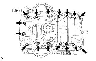
| 49. REMOVE NO. 2 OIL PAN SUB-ASSEMBLY |
 |
Remove the 15 bolts and 2 nuts.
 |
Insert the blade of SST between the oil pans. Cut through the applied sealer and remove the No. 2 oil pan.
| 50. REMOVE OIL PAN SUB-ASSEMBLY |
 |
Remove the 14 bolts and 2 nuts.
 |
Remove the oil pan by prying between the oil pan and cylinder block with a screwdriver.
| 51. REMOVE OIL PAN BAFFLE PLATE |
 |
Remove the 8 bolts and baffle plate.
| 52. REMOVE OIL STRAINER SUB-ASSEMBLY |
 |
Remove the 2 bolts, oil strainer and O-ring.
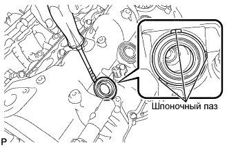
| 53. REMOVE ENGINE REAR OIL SEAL RETAINER |
 |
Remove the 6 bolts.
 |
Using a screwdriver, pry out the oil seal retainer.
| 54. REMOVE OIL DRAIN PIPE SUB-ASSEMBLY |
 |
Remove the bolt and oil drain pipe.
Remove the O-ring.
| 55. REMOVE NO. 1 VENTILATION CONNECTOR |
 |
Remove the ventilation connector.
