БЛОК ДВИГАТЕЛЯ > ПОВТОРНАЯ СБОРКА |
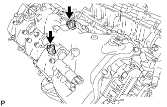
| 1. INSTALL NO. 1 VENTILATION CONNECTOR |
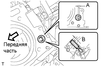 |
Install the No. 1 ventilation connector as shown in the illustration.
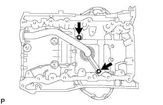
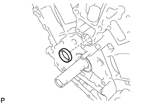
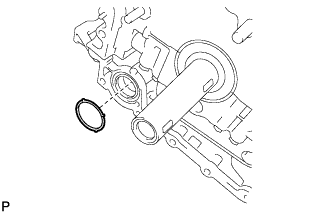
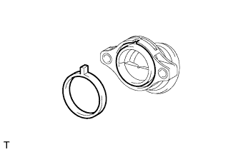
| 2. INSTALL OIL DRAIN PIPE SUB-ASSEMBLY |
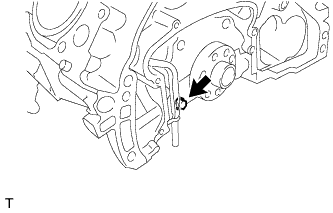 |
Apply a light coat of engine oil to a new O-ring.
Install the new O-ring to the drain pipe.
Install the oil drain pipe with the bolt.
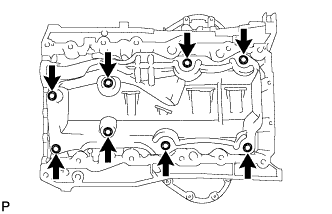
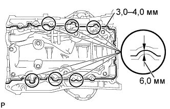
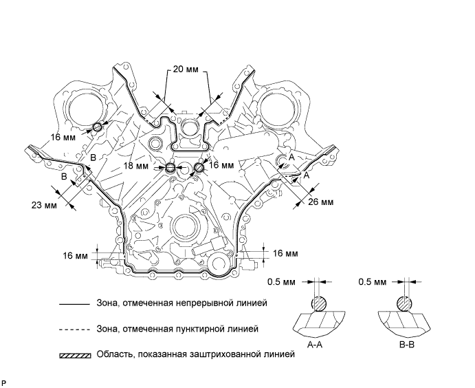
| 3. INSTALL ENGINE REAR OIL SEAL RETAINER |
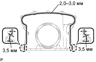 |
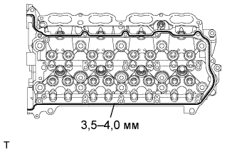
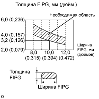
Apply seal packing in a continuous line as shown in the illustration.
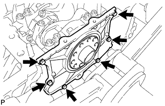 |
Install the oil seal retainer with the 6 bolts.
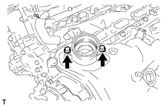
| 4. INSTALL OIL STRAINER SUB-ASSEMBLY |
 |
Apply a light coat of engine oil to a new O-ring.
Install the new O-ring to the oil strainer.
Install the oil strainer with the 2 bolts.
| 5. INSTALL OIL PAN BAFFLE PLATE |
 |
Install the baffle plate with the 8 bolts.
| 6. INSTALL OIL PAN SUB-ASSEMBLY |
 |
Apply seal packing in a continuous line as shown in the illustration.
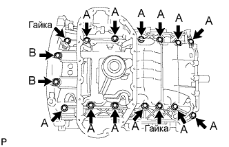 |
Install the oil pan with the 14 bolts and 2 nuts.
| 7. INSTALL NO. 2 OIL PAN SUB-ASSEMBLY |
 |
Apply seal packing in a continuous line as shown in the illustration.
 |
Install the oil pan with the 15 bolts and 2 nuts.
| 8. INSTALL OIL PAN PROTECTOR |
 |
Install the protector with the 2 nuts.
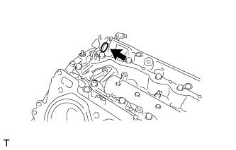
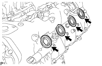
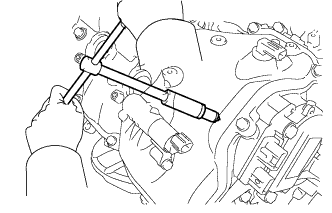
| 9. INSTALL VENTILATION PIPE GASKET |
 |
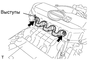
Using SST, evenly tap in a new ventilation pipe gasket until its surface is flush with the lip of the ventilation pipe.
| 10. INSTALL NO. 1 HEAT EXCHANGER COVER |
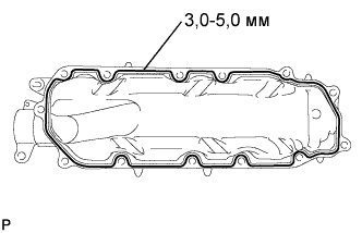 |
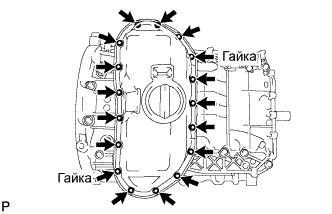
Apply seal packing in a continuous line as shown in the illustration.
 |
Install the heat exchanger cover with the 11 bolts and 2 nuts.
| 11. INSTALL OIL RETURN PIPE GASKET |
 |
Install a new oil return pipe gasket.
| 12. INSTALL CYLINDER BLOCK WATER JACKET SPACER |
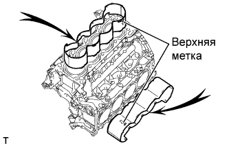 |
Install the 2 water jacket spacers as shown in the illustration.
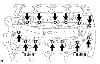
| 13. INSTALL CYLINDER HEAD SUB-ASSEMBLY (for Bank 1) |
Check the piston protrusions for each cylinder.
Clean the cylinder block with solvent.
Set the piston of the cylinder to be measured to slightly ATDC.
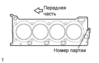 |
Place the cylinder head gasket on the cylinder block surface with the front face of the Lot No. stamp upward.
Place the cylinder head on the cylinder block.
Apply a light coat of engine oil to the threads and under the heads of the cylinder head bolts.
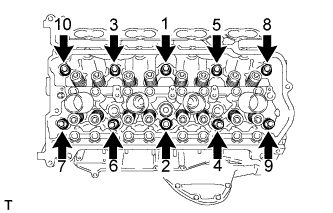 |
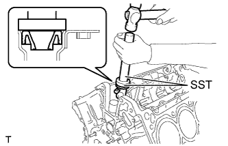
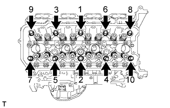
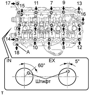
Step 1:
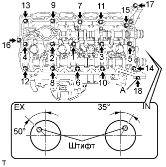
Using a 10 mm bi-hexagon wrench, install and uniformly tighten the 10 cylinder head bolts with the plate washers in several steps, in the sequence shown in the illustration.
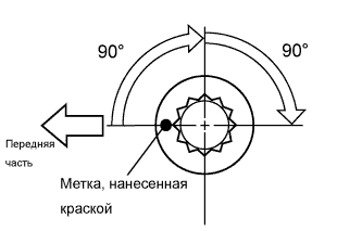 |
Step 2:
Mark the cylinder head bolt head with paint as shown in the illustration.
Tighten the cylinder head bolts another 90° in the sequence shown in step 1.
Step 3:
Tighten the cylinder head bolts by an additional 90° in the sequence shown in step 1.
Check that the painted marks are now facing rearward.
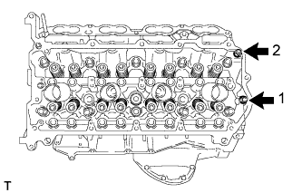 |
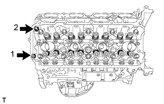
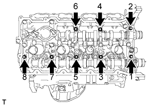
Uniformly install the 2 bolts in the sequence shown in the illustration.
| 14. INSTALL CYLINDER HEAD SUB-ASSEMBLY (for Bank 2) |
Check the piston protrusions for each cylinder.
Clean the cylinder block with solvent.
Set the piston of the cylinder to be measured to slightly ATDC.
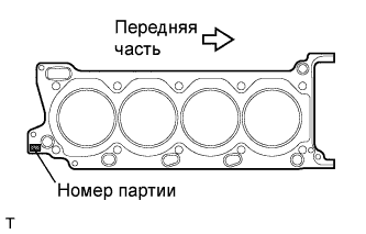 |
Place the cylinder head gasket on the cylinder block surface with the front face of the Lot No. stamp upward.
Place the cylinder head on the cylinder block.
Apply a light coat of engine oil to the threads and under the heads of the cylinder head bolts.
 |
Step 1:
Using a 10 mm bi-hexagon wrench, install and uniformly tighten the 10 cylinder head bolts with the plate washers in several steps, in the sequence shown in the illustration.
|
Step 2:
Mark the cylinder head bolt head with paint as shown in the illustration.
Tighten the cylinder head bolts another 90° in the sequence shown in step 1.
Step 3:
Tighten the cylinder head bolts by an additional 90° in the sequence shown in step 1.
Check that the painting marks are now facing rearward.
 |
Uniformly install the 2 cylinder head bolts.
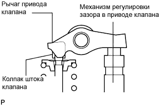
| 15. INSTALL VALVE STEM CAP |
Apply a light coat of engine oil to the valve stem caps.
Install the 32 valve stem caps to the cylinder head.
| 16. INSTALL VALVE LASH ADJUSTER ASSEMBLY |
Be sure to inspect the valve lash adjuster before installing it (see page Нажмите здесь).
Install the 32 valve lash adjusters to the cylinder head.
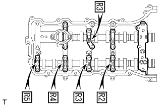
| 17. INSTALL NO. 1 VALVE ROCKER ARM SUB-ASSEMBLY |
Apply engine oil to the lash adjuster tips and valve stem cap ends.
 |
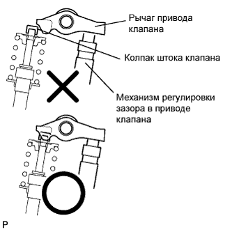
Make sure that the 32 valve rocker arms are installed as shown in the illustration.
| 18. INSTALL CAMSHAFT BEARING CAP (for Bank 2) |
Apply a light coat of engine oil to the camshaft journals, camshaft housings and bearing caps.
Install the No. 1 and No. 2 camshaft to the camshaft housing.
 |
Confirm the marks and numbers on the camshaft bearing caps and place them each in their proper positions and directions.
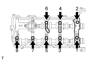 |
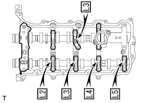
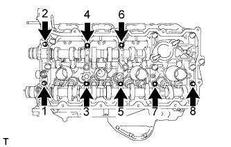
Temporarily install the 8 bolts in the order shown in the illustration.
| 19. INSTALL CAMSHAFT HOUSING SUB-ASSEMBLY (for Bank 2) |
 |
Make sure that the valve rocker arms are installed as shown in the illustration.
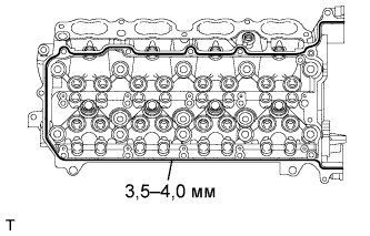 |
Apply seal packing in a continuous line as shown in the illustration.
 |
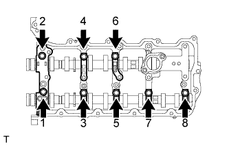
Install the camshaft housing, and install the 12 bolts in the order shown in the illustration.
 |
Tighten the 8 bolts in the order shown in the illustration.
| 20. INSTALL CAMSHAFT BEARING CAP (for Bank 1) |
Apply a light coat of engine oil to the camshaft journals, camshaft housings and bearing caps.
Install the No. 3 and No. 4 camshaft to the camshaft housing.
 |
Confirm the marks and numbers on the camshaft bearing caps and place them each in their proper positions and directions.
 |
Temporarily install the 8 bolts in the order shown in the illustration.
| 21. INSTALL CAMSHAFT HOUSING SUB-ASSEMBLY (for Bank 1) |
|
Make sure that the valve rocker arms are installed as shown in the illustration.
 |
Apply seal packing in a continuous line as shown in the illustration.
 |
Install the camshaft housing, and install the 12 bolts in the order shown in the illustration.
 |
Tighten the 8 bolts in the order shown in the illustration.
| 22. INSTALL CRANKSHAFT TIMING GEAR KEY |
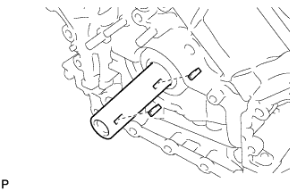 |
Install the 2 timing gear keys.
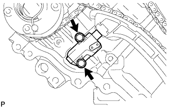
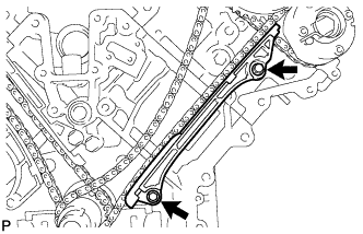
| 23. INSTALL NO. 2 CHAIN TENSIONER ASSEMBLY |
 |
Install the chain tensioner with the 2 bolts.
While raising up the No. 2 chain tensioner, insert a pin of φ1.0 mm (0.039 in.) into the hole to fix it in place.
| 24. INSTALL CHAIN SUB-ASSEMBLY (for Bank 2) |
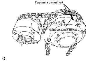 |
Align the No. 1 chain's orange mark plates with the camshaft timing gear's timing mark, and attach the chain to the gear as shown in the illustration.
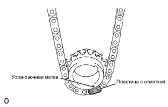 |
Align the No. 1 chain's orange mark plate with the crankshaft timing gear's timing mark, and attach the chain to the gear as shown in the illustration.
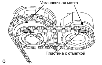 |
Align the No. 2 chain's mark plates (yellow) with the timing marks of the camshaft timing gear assembly and camshaft timing exhaust gear assembly, and attach the No. 2 chain to the gears as shown in the illustration.
Install the crankshaft timing gear to the crankshaft.
Align and attach the knock pin of the No. 1 camshaft with the pin hole of the camshaft timing gear assembly.
Using the hexagonal portion of the No. 2 camshaft, align and attach the knock pin of the No. 2 camshaft with the pin hole of the camshaft timing exhaust gear assembly.
Remove the pin from the No. 2 chain tensioner.
| 25. INSTALL NO. 1 CHAIN VIBRATION DAMPER (for Bank 2) |
 |
Install the vibration damper with the 2 bolts.
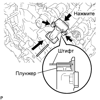
| 26. INSTALL CHAIN TENSIONER SLIPPER (for Bank 2) |
| 27. INSTALL NO. 1 CHAIN TENSIONER ASSEMBLY (for Bank 2) |
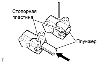 |
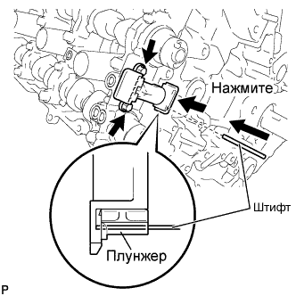
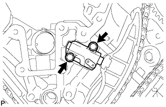
Move the stopper plate upward to release the lock, and push the plunger deep into the tensioner.
Move the stopper plate downward to set the lock, and insert a hexagon wrench into the hole of the stopper plate.
 |
Install the chain tensioner with the 2 bolts.
Remove the hexagon wrench from the chain tensioner.
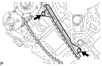
| 28. INSTALL NO. 3 CHAIN TENSIONER ASSEMBLY |
 |
Install the chain tensioner with the 2 bolts.
While pushing down the No. 2 chain tensioner, insert a pin of φ1.0 mm (0.039 in.) into the hole to fix it in place.
| 29. INSTALL CHAIN SUB-ASSEMBLY (for Bank 1) |
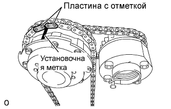 |
Align the No. 1 chain's orange mark plates with the camshaft timing gear's timing mark, and attach the chain to the gear as shown in the illustration.
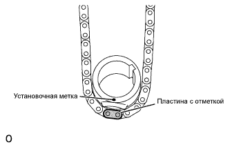 |
Align the No. 1 chain's orange mark plate with the crankshaft timing gear's timing mark, and attach the chain to the gear as shown in the illustration.
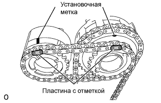 |
Align the No. 2 chain's mark plates (yellow) with the timing marks of the camshaft timing gear assembly and camshaft timing exhaust gear assembly, and attach the No. 2 chain to the gears as shown in the illustration.
Install the crankshaft timing gear to the crankshaft.
Align and attach the knock pin of the No. 3 camshaft with the pin hole of the camshaft timing gear assembly.
Using the hexagonal portion of the No. 4 camshaft, align and attach the knock pin of the No. 4 camshaft with the pin hole of the camshaft timing exhaust gear assembly.
Remove the pin from the No. 2 chain tensioner.
| 30. INSTALL CHAIN TENSIONER SLIPPER (for Bank 1) |
| 31. INSTALL NO. 1 CHAIN TENSIONER ASSEMBLY (for Bank 1) |
|
Move the stopper plate upward to release the lock, and push the plunger deep into the tensioner.
Move the stopper plate downward to set the lock, and insert a hexagon wrench into the hole of the stopper plate.
 |
Install a new gasket and chain tensioner with the 2 bolts.
| 32. INSTALL NO. 1 CHAIN VIBRATION DAMPER (for Bank 1) |
 |
Install the vibration damper with the 2 bolts.
Remove the hexagon wrench from the No. 1 chain tensioner.
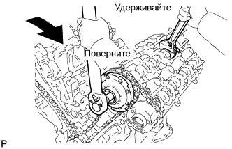
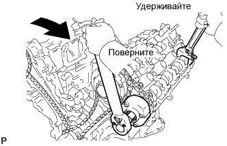
| 33. TIGHTEN CAMSHAFT TIMING GEAR ASSEMBLY |
for Bank 1:
 |
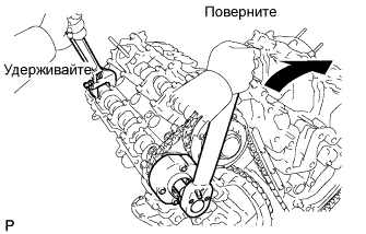
Using a wrench, hold the hexagonal portion of the No. 3 camshaft.
Using a 12 mm socket hexagon wrench, tighten the camshaft timing gear assembly with a new bolt.
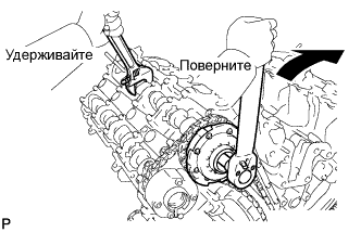
 |
Using a wrench to hold the hexagonal portion of the No. 4 camshaft, tighten the camshaft timing exhaust gear assembly with the bolt.
for Bank 2:
 |
Using a wrench, hold the hexagonal portion of the No. 1 camshaft.
Using a 12 mm socket hexagon wrench, tighten the camshaft timing gear assembly with a new bolt.
 |
Using a wrench to hold the hexagonal portion of the No. 2 camshaft, tighten the camshaft timing exhaust gear assembly with the bolt.
| 34. CHECK NO. 1 CYLINDER TO TDC / COMPRESSION |
Temporarily install the crankshaft pulley bolt.
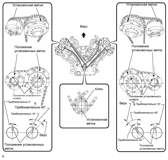
Rotate the crankshaft clockwise, and check that the timing marks on the crankshaft timing gear and camshaft timing gears are as shown in the illustration.
Remove the crankshaft pulley bolt.
| 35. INSTALL WATER INLET PIPE |
 |
Apply soapy water to 2 new O-rings and install them to the inlet pipe.
Install the inlet pipe to the No. 1 heat exchanger cover.
| 36. INSTALL WATER PUMP |
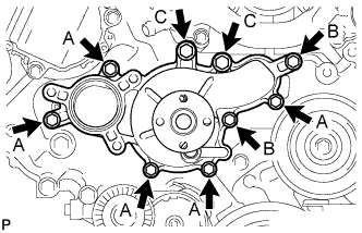 |
Install the water pump and gasket with the 9 bolts as shown the illustration.
| 37. INSTALL TIMING CHAIN COVER SUB-ASSEMBLY |
 |
Install a new oil pump gasket.
 |
Install a new O-ring.
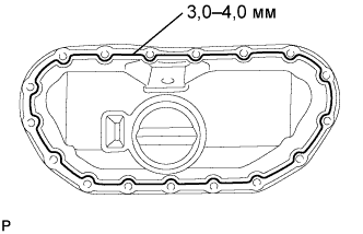
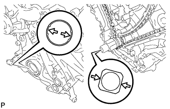
Apply seal packing in a continuous line to the timing chain cover as shown in the following illustration.
 |
| Area | Seal packing diameter | Application position from inside edge of cover |
| Continuous Line Area | 3.0 to 4.0 mm (0.1181 to 0.1575 in.) | 2.5 mm (0.098 in.) |
| Dashed Line Area | 6.4 mm (0.2520 in.) or more, or within OK area shown in illustration | 0.5 mm (0.020 in.) |
| Diagonal Line Area | 3.0 to 4.0 mm (0.1181 to 0.1575 in.) | 5.5 mm (0.217 in.) |
 |
Align the oil pump's drive rotor spline and the crankshaft as shown in the illustration. Install the spline and chain cover to the crankshaft.
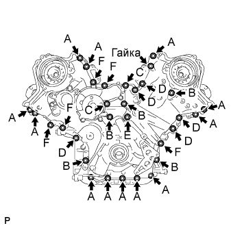 |
Temporarily tighten the timing chain cover with the 30 bolts and nut.
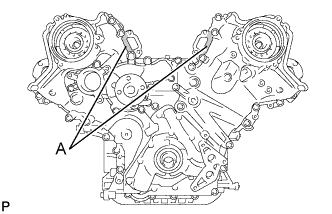
| Item | Length | Thread diameter |
| Bolt A | 25 mm (0.984 in.) | 8 mm (0.315 in.) |
| Bolt B | 55 mm (2.165 in.) | 8 mm (0.315 in.) |
| Bolt C | 70 mm (2.756 in.) | 8 mm (0.315 in.) |
| Bolt D | 35 mm (1.378 in.) | 10 mm (0.394 in.) |
| Bolt E | 55 mm (2.165 in.) | 10 mm (0.394 in.) |
| Bolt F | 80 mm (3.150 in.) | 10 mm (0.394 in.) |
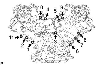 |
Tighten the 11 bolts in several steps, in the sequence shown in the illustration.
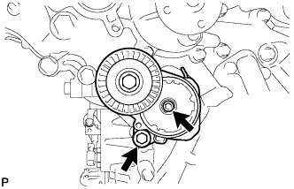 |
Temporarily tighten the belt tensioner with the standard bolt and 6 mm hexagon wrench bolt.
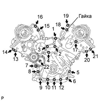 |
Tighten the 21 bolts and nut in several steps, in the sequence shown in the illustration.
 |
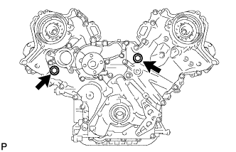 |
Install the 2 new gaskets and 2 plugs.
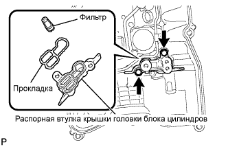
| 38. INSTALL OIL CONTROL VALVE FILTER |
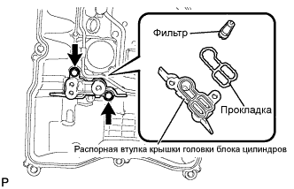 |
for Bank 1:
Install the valve filter in the cylinder head.
Install a new gasket and the cylinder head cover spacer with the 2 bolts.
for Bank 2:
 |
Install the valve filter in the cylinder head.
Install a new gasket and the cylinder head cover spacer with the 2 bolts.
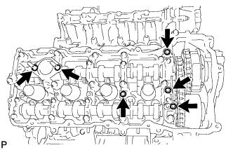
| 39. INSTALL CYLINDER HEAD COVER SUB-ASSEMBLY (for Bank 1) |
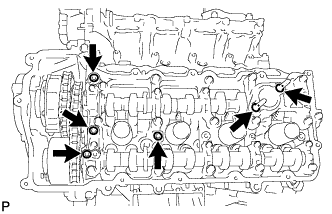 |
Install 4 new gaskets and 2 new O-rings to the camshaft bearing caps (No. 2, No. 3, No. 7).
Install a new gasket to the cylinder head cover.
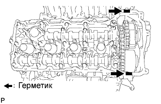
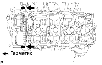 |
Apply seal packing as shown the illustration.
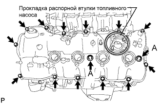 |
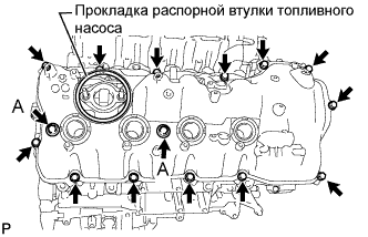
Install the cylinder head cover with 2 new seal washers and the 15 bolts.
Install the fuel pump spacer gasket.
| 40. INSTALL CYLINDER HEAD COVER SUB-ASSEMBLY (for Bank 2) |
 |
Install 4 new gaskets and 2 new O-rings to the camshaft bearing caps. (No. 1, No. 3, No. 6).
Install a new gasket to the cylinder head cover.
 |
Apply seal packing as shown the illustration.
 |
Install the cylinder head cover with 2 new seal washers and the 15 bolts.
Install the fuel pump spacer gasket.
| 41. INSTALL SPARK PLUG TUBE GASKET |
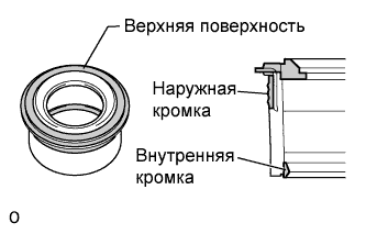 |
Perform a visual inspection on the spark plug tube gasket.
| Inspection Area | Inspection Result |
| Upper surface | No scratches or deformation |
| Outer lip | No scratches or deformation |
| Inner lip | No scratches |
 |
Install the 8 plug tube gaskets to the cylinder head cover.
| 42. INSTALL CRANKSHAFT PULLEY |
Align the pulley set key with the key groove of the pulley, and slide on the pulley.
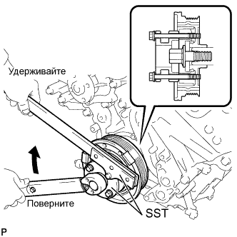 |
Using SST, install the pulley bolt.
| 43. INSTALL FRONT WATER BY-PASS JOINT |
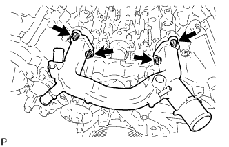 |
Install the water by-pass joint and 2 new gaskets with the 4 nuts.
| 44. INSTALL OIL FILTER BRACKET |
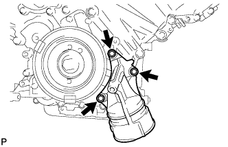 |
Install 2 new gaskets and the filter bracket with the 3 bolts.
| 45. INSTALL OIL FILTER ELEMENT |
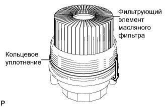 |
Clean the inside of the oil filter cap, the threads and O-ring groove.
Apply a small amount of engine oil to a new O-ring and install it to the oil filter cap.
Set a new oil filter element to the oil filter cap.
Remove any dirt or foreign matter from the installation surface of the engine.
Apply a small amount of engine oil to the O-ring again and temporarily install the oil filter cap.
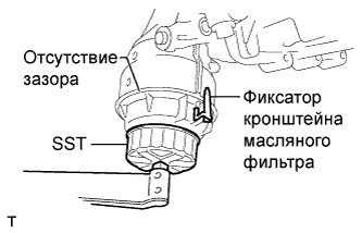 |
Using SST, tighten the oil filter cap.
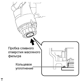 |
Apply a small amount of engine oil to a new drain plug O-ring, and install it to the oil filter cap.
Install the oil filter drain plug.
| 46. INSTALL CAMSHAFT TIMING CONTROL MOTOR (for Bank 1) |
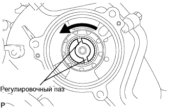 |
Turn the camshaft timing gear assembly's eccentric shaft index slot in the counterclockwise direction by hand, and set it to the maximum retard angle position.
Install a new O-ring to the timing chain cover.
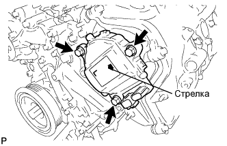 |
Align the joint of the camshaft timing control motor and the keyway of the camshaft timing gear assembly, and install the motor with the 3 bolts.
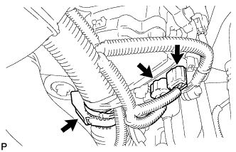 |
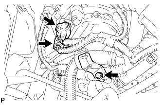
Connect the 2 camshaft timing control motor connectors and engine wire clamp.
| 47. INSTALL CAMSHAFT TIMING CONTROL MOTOR (for Bank 2) |
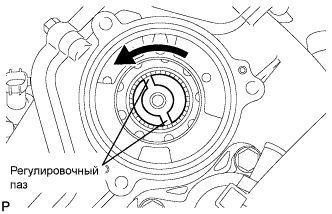 |
Turn the camshaft timing gear assembly's eccentric shaft index slot in the counterclockwise direction by hand, and set it to the maximum retard angle position.
Install a new O-ring to the timing chain cover.
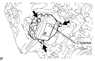 |
Align the joint of the camshaft timing control motor and the keyway of the camshaft timing gear assembly, and install the motor with the 3 bolts.
 |
Install the engine wire bracket with the bolt.
Connect the 2 camshaft timing control motor connectors.
| 48. INSTALL CYLINDER BLOCK WATER DRAIN COCK SUB-ASSEMBLY |
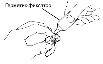 |
Apply adhesive to 2 or 3 threads of the drain cock.
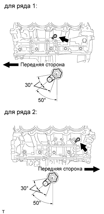 |
Install the water drain cocks as shown in the illustration.
Install the water drain cock plugs to the water drain cocks.
| 49. INSTALL CAMSHAFT TIMING OIL CONTROL VALVE ASSEMBLY |
for Bank 1:
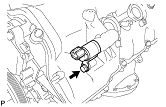 |
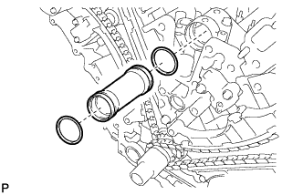
Apply a light coat of engine oil to a new O-ring.
Install the O-ring to the oil control valve.
Install the oil control valve with the bolt.
for Bank 2:
 |
Apply a light coat of engine oil to a new O-ring.
Install the O-ring to the oil control valve.
Install the oil control valve with the bolt.
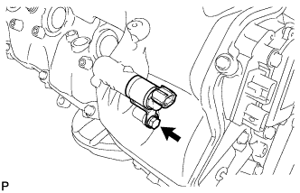
| 50. INSTALL CRANKSHAFT POSITION SENSOR |
 |
Install the crankshaft position sensor with the bolt.
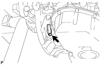
| 51. INSTALL CAMSHAFT POSITION SENSOR |
 |
Install the camshaft position sensor with the bolt.
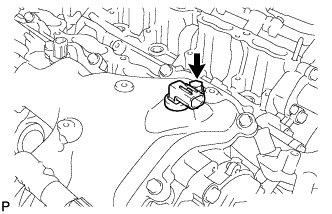
| 52. INSTALL VVT SENSOR |
for Bank 1:
 |
Install the 2 VVT sensors with the 2 bolts.
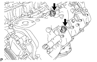
for Bank 2:
 |
Install the 2 VVT sensors with the 2 bolts.
| 53. INSTALL SPARK PLUG |
 |
Using a 16 mm plug wrench, install the 8 spark plugs.
| 54. INSTALL OIL FILLER CAP HOUSING |
 |
Align the protrusion of a new gasket with the cutout of the oil filler cap housing, and install the gasket to the housing.
 |
Install the cap housing with the 2 bolts.
| 55. INSTALL OIL FILLER CAP SUB-ASSEMBLY |
