ГОЛОВКА БЛОКА ЦИЛИНДРОВ > ПРОВЕРКА |
| 1. INSPECT CYLINDER HEAD SUB-ASSEMBLY |
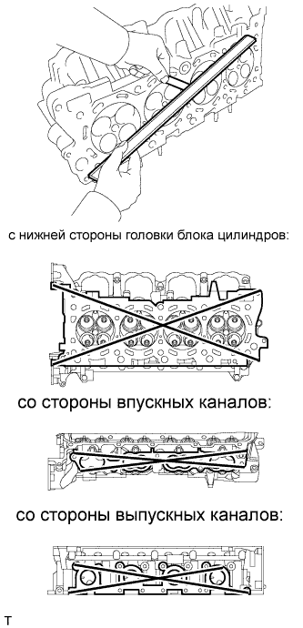 |
Using a precision straightedge and feeler gauge, measure the warpage of the contact surfaces of the cylinder block and manifold.
| Item | Specified Condition |
| Cylinder head lower side | 0.05 mm (0.0020 in.) |
| Intake side | 0.08 mm (0.0031 in.) |
| Exhaust side | 0.05 mm (0.0020 in.) |
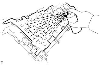 |
Using a dye penetrant, check the intake ports, exhaust ports and cylinder surface for cracks.
If cracked, replace the cylinder head.
| 2. INSPECT INTAKE VALVE |
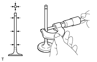 |
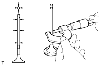
Using a micrometer, measure the diameter of the valve stem.
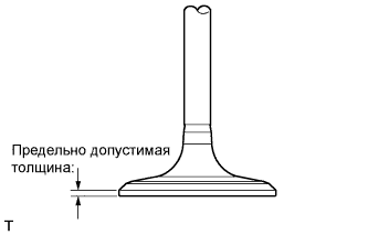 |
Using a vernier caliper, measure the valve head margin thickness.
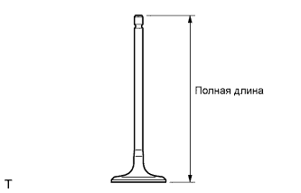 |
Using a vernier caliper, measure the valve's overall length.
| 3. INSPECT EXHAUST VALVE |
 |
Using a micrometer, measure the diameter of the valve stem.
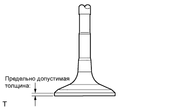 |
Using a vernier caliper, measure the valve head margin thickness.
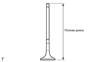 |
Using a vernier caliper, measure the valve's overall length.
| 4. INSPECT INTAKE VALVE SEAT |
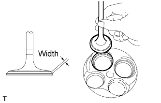 |
Apply a light coat of Prussian blue to the valve face.
Lightly press the valve face against the valve seat.
Check the valve face and valve seat.
Check that the contact surfaces of the valve seat and valve face are in the middle area of their respective surfaces, with the width between 1.1 to 1.5 mm (0.0433 to 0.0591 in.).
If not, correct the valve seat.
Check that the contact surfaces of the valve seat and valve face are even around the entire valve seat.
If not, correct the valve seat.
| 5. INSPECT EXHAUST VALVE SEAT |
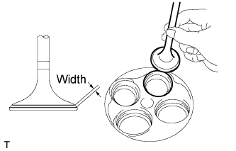 |
Apply a light coat of Prussian blue to the valve face.
Lightly press the valve face against the valve seat.
Check the valve face and valve seat.
Check that the contact surfaces of the valve seat and valve face are in the middle area of their respective surfaces, with the width between 1.1 to 1.5 mm (0.0433 to 0.0591 in.).
If not, correct the valve seat.
Check that the contact surface of the valve seat and valve face are even around the entire valve seat.
If not, correct the valve seat.
| 6. INSPECT COMPRESSION SPRING |
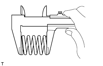 |
Using a vernier caliper, measure the free length of the inner compression spring.
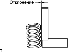 |
Using a steel square, measure the deviation of the inner compression spring.
| 7. INSPECT VALVE GUIDE BUSH OIL CLEARANCE |
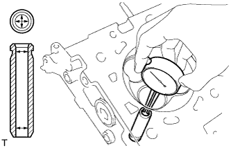 |
Using a caliper gauge, measure the inside diameter of the guide bush.
Subtract the valve stem diameter measurement from the guide bush inside diameter measurement.
| Item | Specified Condition |
| Intake | 0.025 to 0.060 mm (0.0010 to 0.0024 in.) |
| Exhaust | 0.030 to 0.065 mm (0.0012 to 0.0026 in.) |
| Item | Specified Condition |
| Intake | 0.08 mm (0.0031 in.) |
| Exhaust | 0.10 mm (0.0039 in.) |
| 8. INSPECT CAMSHAFT THRUST CLEARANCE |
Inspect the bank 1 camshafts.
Install the bank 1 camshafts.
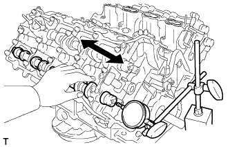 |
Using a dial indicator, measure the thrust clearance while moving the camshaft back and forth.
Inspect the bank 2 camshafts.
Install the bank 2 camshafts.
Using a dial indicator, measure the thrust clearance while moving the camshaft back and forth.
