ДАТЧИК МАССОВОГО РАСХОДА ВОЗДУХА > УСТАНОВКА |
| 1. INSTALL MASS AIR FLOW METER (for Bank 1) |
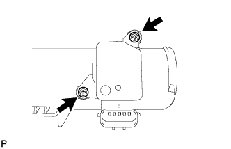 |
Install the MAF meter with the 2 screws.
| 2. REMOVE MASS AIR FLOW METER (for Bank 2) |
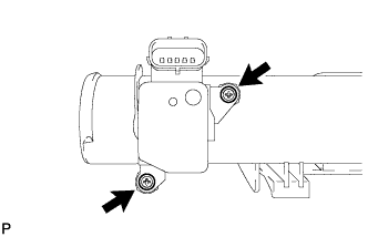 |
Install the MAF meter with the 2 screws.
| 3. INSTALL AIR CLEANER CAP LH |
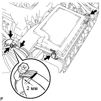 |
Install the air cleaner cap to the air cleaner hose assembly with the hose clamp.
Install the air cleaner cap to the air cleaner case with the 2 clips.
Connect the MAF meter connector.
| 4. INSTALL AIR CLEANER CAP RH |
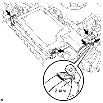 |
Install the air cleaner cap to the air cleaner hose assembly with the hose clamp.
Install the air cleaner cap to the air cleaner case with the 2 clips.
Connect the MAF meter connector.
| 5. INSTALL V-BANK COVER SUB-ASSEMBLY |
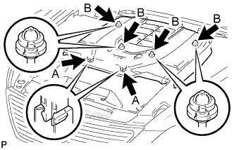 |
After sliding the cover from the vehicle front to the rear to attaching the 2 clips A, attach the 4 clips B and install the V bank cover.
| 6. CONNECT CABLE TO NEGATIVE BATTERY TERMINAL |
| 7. INSTALL COWL TOP VENTILATOR LOUVER RH |
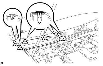 |
Install the 6 clips and cowl top ventilator louver RH.
| 8. PERFORM INITIALIZATION |
Perform initialization (see page Нажмите здесь).
