ГИДРАВЛИЧЕСКИЙ КЛАПАН ИЗМЕНЕНИЯ ФАЗ > УСТАНОВКА |
| 1. INSTALL CAMSHAFT TIMING OIL CONTROL VALVE ASSEMBLY (for Bank 1) |
Apply a light coat of engine oil to a new O-ring, and install it to the oil control valve.
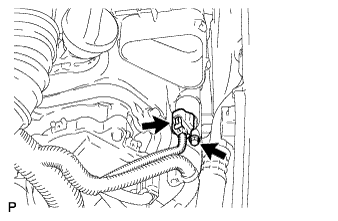 |
Install the oil control valve with the bolt.
Connect the camshaft timing oil control valve connector.
| 2. INSTALL CAMSHAFT TIMING OIL CONTROL VALVE ASSEMBLY (for Bank 2) |
Apply a light coat of engine oil to a new O-ring, and install it to the oil control valve.
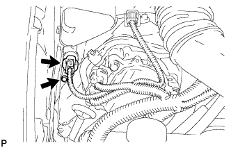 |
Install the oil control valve with the bolt.
Connect the camshaft timing oil control valve connector.
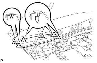
| 3. INSTALL NO. 1 AIR CLEANER INLET |
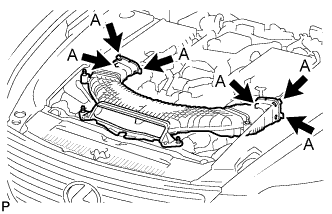 |
Align the holes with the connection areas labeled A, and attach the No. 1 air cleaner inlet.
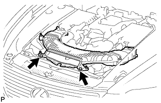 |
Install the No. 1 air cleaner inlet with the 2 bolts.
| 4. INSTALL AIR CLEANER INLET COVER |
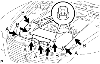 |
Attach the 4 clips B.
Install the air cleaner inlet cover with the 5 clips A.
| 5. INSTALL V-BANK COVER SUB-ASSEMBLY |
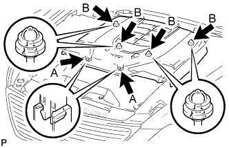 |
After sliding the cover from the vehicle front to the rear to attaching the 2 clips A, attach the 4 clips B and install the V bank cover.
| 6. CONNECT CABLE TO NEGATIVE BATTERY TERMINAL |
| 7. INSTALL COWL TOP VENTILATOR LOUVER RH |
 |
Install the 6 clips and cowl top ventilator louver RH.
| 8. PERFORM INITIALIZATION |
Perform initialization (see page Нажмите здесь).
| 9. DRIVING TEST |
After the engine is warmed up, perform the driving test. Then check that the oil control valve operates normally.
