ГЕНЕРАТОР > УСТАНОВКА

для подготовки Нажмите здесь


1. INSTALL GENERATOR


A149898
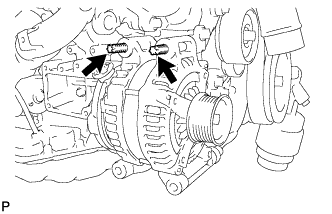
  1. Using an E8 "TORX" socket wrench, set the generator with the 2 stud bolts.

    Момент затяжки: 
    10 Н*м{ 102 кгс*см , 7 фунт-сила-футов }


    A149897
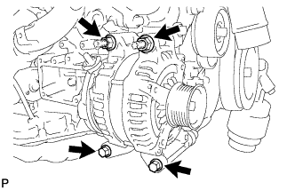
  1. Install the generator with the 2 bolts and 2 nuts.

    Момент затяжки: 
    43 Н*м{ 438 кгс*см , 32 фунт-сила-футов }


    A149896
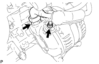
  1. Connect the generator connector.

  1. Connect the harness to the +B terminal with the nut.

    Момент затяжки: 
    12 Н*м{ 122 кгс*см , 9 фунт-сила-футов }


2. INSTALL V-RIBBED BELT


    A149057E01
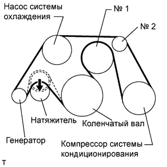
  1. Install the V belt as shown in the illustration.

    ПРИМЕЧАНИЕ:
    Check that the drive belt is properly set to each pulley.


    1. Rotate the tensioner pulley counterclockwise, and then remove the fix bar.


3. INSTALL INTAKE AIR CONNECTOR PIPE


A148828E01
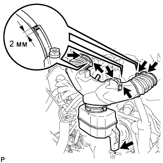
  1. Align the protrusion of the intake air resonator with the cutout of the bracket and insert the protrusion.

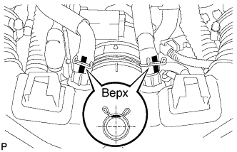
  1. Install the intake air connector pipe with the 3 hose clamps.

    Момент затяжки: 
    4.8 Н*м{ 48 кгс*см , 42 фунт-сила-дюймов } for intake air connector pipe and throttle body
    3.8 Н*м{ 38 кгс*см , 34 фунт-сила-дюймов } for intake air connector pipe and intake air resonator

    ПРИМЕЧАНИЕ:
    Insert the protrusion of the intake air connector pipe into the hole of the hose clamp.

    УКАЗАНИЕ:
    1. The intake air connector pipe and throttle body can be tightened within the range of 4.0 N*m (41 kgf*cm. 35 in.*lbf) to 5.5 N*m (56 kgf*cm. 49 in.*lbf), and the intake air connector pipe and air cleaner assembly can be tightened within the range of 2.0 N*m (20 kgf*cm. 18 in.*lbf) to 5.5 N*m (56 kgf*cm. 49 in.*lbf).
    2. When tightening the hose clamp, make sure the hose clamp's end is within the painted white line (width: 2 mm).


    A148829E01
  1. Connect the No. 1 ventilation hose and No. 2 ventilation hose to the intake air connector pipe.

    ПРИМЕЧАНИЕ:
    1. Position the claws of the clamps as shown in the illustration.
    2. Install the clips so that they are within the hose's paint marks.


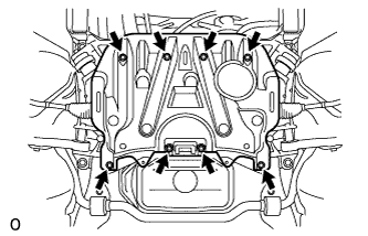
4. INSTALL NO. 2 ENGINE UNDER COVER


    A149478E01
  1. Install the under cover with the 8 bolts.

    Момент затяжки: 
    10 Н*м{ 102 кгс*см , 7 фунт-сила-футов } for Bolt A

    Момент затяжки: 
    27 Н*м{ 275 кгс*см , 20 фунт-сила-футов } for Bolt B


5. INSTALL FRONT SUSPENSION MEMBER PROTECTOR LOWER


    A149477
  1. Install the suspension member protector with the 8 bolts.

    Момент затяжки: 
    10 Н*м{ 102 кгс*см , 7 фунт-сила-футов }


6. INSTALL NO. 1 ENGINE UNDER COVER


    A132845
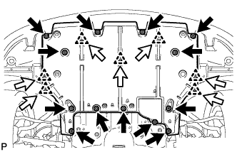
  1. Install the cover with the 7 clips and 13 screws.


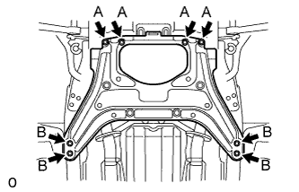
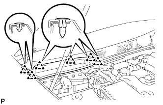
7. INSTALL NO. 1 AIR CLEANER INLET


A158334E01
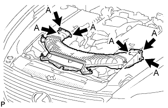
  1. Align the holes with the connection areas labeled A, and attach the No. 1 air cleaner inlet.


    A148822
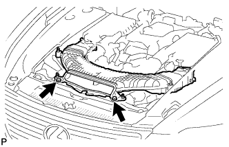
  1. Install the No. 1 air cleaner inlet with the 2 bolts.

    Момент затяжки: 
    5.0 Н*м{ 51 кгс*см , 44 фунт-сила-дюймов }


8. INSTALL AIR CLEANER INLET COVER


A148821E01
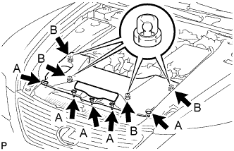
  1. Attach the 4 clips B.

    ПРИМЕЧАНИЕ:
    1. Make sure the clips are attached securely.
    2. Attaching the clips forcefully or hitting the top of the clips may damage them.

  1. Install the air cleaner inlet cover with the 5 clips A.


9. INSTALL V-BANK COVER SUB-ASSEMBLY


A148820E01
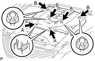
  1. After sliding the cover from the vehicle front to the rear to attaching the 2 clips A, attach the 4 clips B and install the V bank cover.

    ПРИМЕЧАНИЕ:
    1. Make sure the clips are attached securely.
    2. Attaching the clips forcefully or hitting the top of the clips may damage them.


10. CONNECT CABLE TO NEGATIVE BATTERY TERMINAL


11. INSTALL COWL TOP VENTILATOR LOUVER RH


E139771
  1. Install the 6 clips and cowl top ventilator louver RH.

    ПРИМЕЧАНИЕ:
    If the cowl top ventilator louver RH is not properly installed, water may leak into the engine room and cause malfunctions. Therefore, make sure the cowl top ventilator louver RH is installed properly.


12. PERFORM INITIALIZATION
  1. Perform initialization (see page Нажмите здесь).

    ПРИМЕЧАНИЕ:
    Certain systems need to be initialized after disconnecting and reconnecting the cable from the negative (-) battery terminal.