РАСПРЕДВАЛ (для ряда 1) > ПРОВЕРКА |
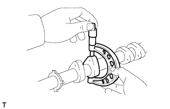
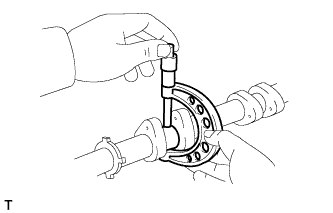
| 1. INSPECT CAMSHAFT TIMING GEAR ASSEMBLY |
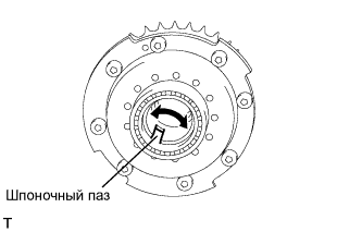 |
Using vernier calipers, measure the width of the camshaft timing gear assembly's eccentric shaft cutout.
Rotate the keyway part of the camshaft timing gear assembly's eccentric shaft by hand.
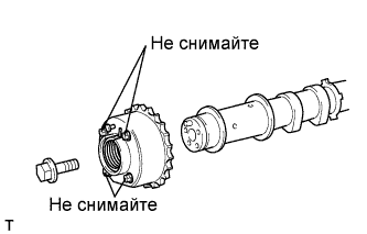
| 2. INSPECT CAMSHAFT TIMING EXHAUST GEAR ASSEMBLY |
Install the camshaft bearing cap (see page Нажмите здесь).
Install the camshaft housing (see page Нажмите здесь).
Apply a light coat of engine oil on the camshaft and camshaft timing exhaust gear.
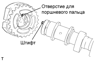 |
Using the hexagonal portion of the camshaft, align and attach the knock pin of the camshaft with the pin hole of the camshaft timing exhaust gear assembly.
 |
Apply a light coat of engine oil on the threads and under the heads of the bolt.
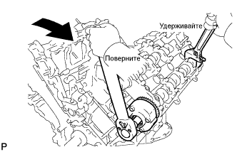 |
Using a wrench to hold the hexagonal portion of the camshaft, install the camshaft timing exhaust gear assembly with the bolt.
Remove the camshaft bearing cap (see page Нажмите здесь).
Check the lock of the camshaft timing gear.
Make sure that the camshaft timing exhaust gear is locked.
 |
Release the lock pin.
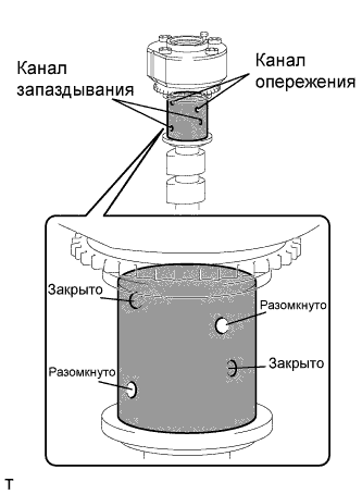
Cover the 4 oil paths of the cam journal with vinyl tape as shown in the illustration.
Prick a hole in the tape placed on the advance side path. Prick a hole in the tape placed on the retard side path on the opposite side to that of the advance side path, as shown in the illustration.
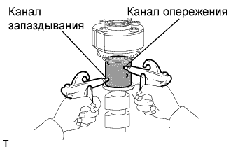 |
Apply approximately 200 kPa (2.0 kgf/cm2, 28 psi) of air pressure to the 2 broken paths (the advance side path and the retard side path).
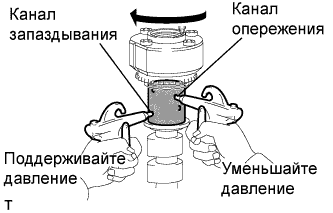 |
Check that the camshaft timing gear revolves in the retard direction when reducing the air pressure applied to the advance side path.
When the camshaft timing gear reaches the most retarded position, release the air pressure from the advance side path and retard side path, in that order.
Check for smooth rotation.
Turn the camshaft timing gear within its movable range (21°) 2 or 3 times, but do not turn it to the most advanced position. Make sure that the gear turns smoothly.
Check the lock in the most advanced position.
Confirm that the camshaft timing gear is locked at the most advanced position.
Install the camshaft bearing cap (see page Нажмите здесь).
Install the camshaft housing (see page Нажмите здесь).
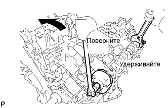 |
Hold the hexagonal portion of the camshaft with a wrench and loosen the bolt.
Remove the camshaft bearing cap (see page Нажмите здесь).
|
Remove the flange bolt and camshaft timing exhaust gear.
| 3. INSPECT CAMSHAFT SUB-ASSEMBLY |
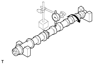 |
Inspect the camshaft for runout.
Place the camshaft on V-blocks.
Using a dial indicator, measure the circle runout at the center journal.
 |
Using a micrometer, measure the cam lobe height.
| Item | Specified Condition |
| Intake | 44.293 to 44.443 mm (1.7438 to 1.7497 in.) |
| Exhaust | 44.316 to 44.466 mm (1.7447 to 1.7506 in.) |
| Item | Specified Condition |
| Intake | 44.243 mm (1.7419 in.) |
| Exhaust | 44.266 mm (1.7428 in.) |
 |
Using a micrometer, measure the journal diameter.
| Item | Specified Condition |
| No. 1 journal | 29.956 to 29.970 mm (1.1794 to 1.1799 in.) |
| Other journal | 25.959 to 25.975 mm (1.0220 to 1.0226 in.) |
| 4. INSPECT CAMSHAFT OIL CLEARANCE |
Clean the bearing caps, camshaft housing and camshaft journals.
Place the camshafts on the camshaft housing.
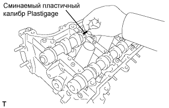 |
Lay a strip of Plastigage across each of the camshaft journals.
Install the bearing caps (see page Нажмите здесь).
Install the camshaft housing (see page Нажмите здесь).
Remove the bearing caps (see page Нажмите здесь).
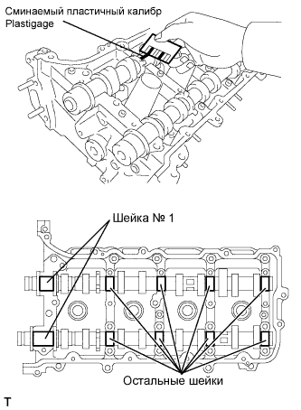 |
Measure the Plastigage at its widest point.
| Item | Specified Condition |
| No. 1 journal | 0.040 to 0.079 mm (0.0016 to 0.0031 in.) |
| Other journal | 0.025 to 0.062 mm (0.0010 to 0.0024 in.) |
| Item | Specified Condition |
| No. 1 journal | 0.10 mm (0.0039 in.) |
| Other journal | 0.09 mm (0.0035 in.) |
