БЛОК ДВИГАТЕЛЯ > ПРОВЕРКА |
| 1. INSPECT NO. 1 VALVE ROCKER ARM SUB-ASSEMBLY |
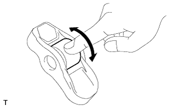 |
Turn the roller by hand to check that it turns smoothly.
If the roller does not turn smoothly, replace the valve rocker arm.
| 2. INSPECT VALVE LASH ADJUSTER ASSEMBLY |
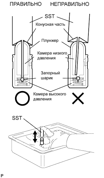 |
Place the lash adjuster into a container full of new engine oil.
Insert SST's tip into the lash adjuster's plunger and use the tip to press down on the check ball inside the plunger.
Squeeze SST and the lash adjuster together to move the plunger up and down 5 to 6 times.
Check the movement of the plunger and bleed air.
After bleeding the air, remove SST. Then try to quickly and firmly press the plunger with your fingers.
| 3. INSPECT CYLINDER HEAD SET BOLT |
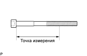 |
Using a vernier caliper, measure the minimum diameter of the elongated thread at the measuring point.
| 4. INSPECT CAMSHAFT |
Inspect the bank 1 camshaft (see page Нажмите здесь).
Inspect the bank 2 camshaft (see page Нажмите здесь).
| 5. INSPECT CAMSHAFT TIMING GEAR ASSEMBLY |
Inspect the bank 1 camshaft timing gear (see page Нажмите здесь).
Inspect the bank 2 camshaft timing gear (see page Нажмите здесь).
| 6. INSPECT CAMSHAFT TIMING EXHAUST GEAR ASSEMBLY |
Inspect the bank 1 camshaft timing exhaust gear (see page Нажмите здесь).
Inspect the bank 2 camshaft timing exhaust gear (see page Нажмите здесь).
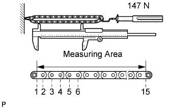
| 7. INSPECT CHAIN SUB-ASSEMBLY |
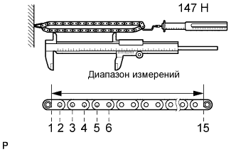 |
Using a spring scale, pull the chain with a force of 147 N (15 kgf, 33 lbf) as shown the illustration.
Using a vernier caliper, measure the length of 15 pins.
| 8. INSPECT NO. 2 CHAIN SUB-ASSEMBLY |
 |
Using a spring scale, pull the chain with a force of 147 N (15 kgf, 33 lbf) as shown the illustration.
Using a vernier caliper, measure the length of 15 pins.
| 9. INSPECT CRANKSHAFT TIMING SPROCKET |
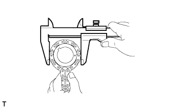 |
Wrap the chain around the sprocket.
Using a vernier caliper, measure the sprocket diameter with the chain.
| 10. INSPECT CRANKSHAFT TIMING SPROCKET LH |
 |
Wrap the chain around the sprocket.
Using a vernier caliper, measure the sprocket diameter with the chain.
| 11. INSPECT NO. 1 CHAIN TENSIONER ASSEMBLY |
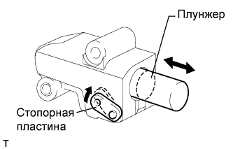 |
Move the stopper plate upward to release the lock. Push the plunger and check that it moves smoothly.
If necessary, replace the chain tensioner.
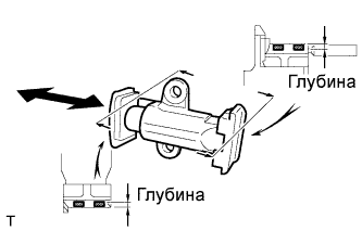
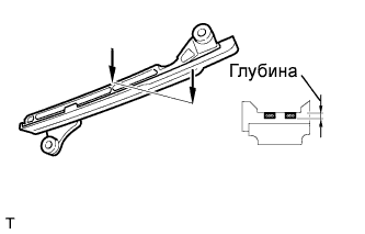
| 12. INSPECT NO. 2 CHAIN TENSIONER ASSEMBLY |
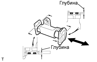 |
Check that the plunger moves smoothly.
Measure the worn depth of the chain tensioner.
| 13. INSPECT NO. 3 CHAIN TENSIONER ASSEMBLY |
 |
Check that the plunger moves smoothly.
Measure the worn depth of the chain tensioner.
| 14. INSPECT CHAIN TENSIONER SLIPPER |
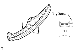 |
for Bank 1:
Measure the worn depth of the chain tensioner slipper.
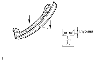 |
for Bank 2:
Measure the worn depth of the chain tensioner slipper.
| 15. INSPECT NO. 1 CHAIN VIBRATION DAMPER |
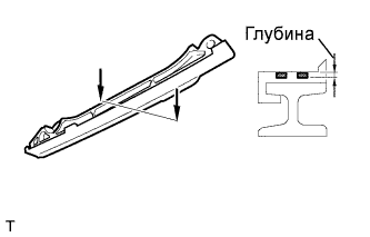 |
for Bank 1:
Measure the worn depth of the chain vibration damper.
 |
for Bank 2:
Measure the worn depth of the chain vibration damper.
| 16. INSPECT CYLINDER HEAD SUB-ASSEMBLY |
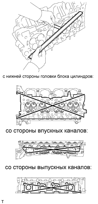 |
Using a precision straightedge and feeler gauge, measure the warpage of the contact surfaces of the cylinder block and manifold.
| Item | Specified Condition |
| Cylinder head lower side | 0.05 mm (0.0020 in.) |
| Intake side | 0.08 mm (0.0031 in.) |
| Exhaust side | 0.05 mm (0.0020 in.) |
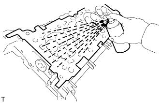 |
Using a dye penetrant, check the intake ports, exhaust ports and cylinder surface for cracks.
If cracked, replace the cylinder head.
| 17. INSPECT CAMSHAFT OIL CLEARANCE |
Inspect the bank 1 camshaft oil clearance (see page Нажмите здесь).
Inspect the bank 2 camshaft oil clearance (see page Нажмите здесь).
