DTC P1360 "A" Camshaft Position Actuator Circuit Open, Low, High Bank1 |
DTC P1361 "A" Camshaft Position Actuator Circuit Open, Low, High Bank2 |
| DTC No. | DTC Detection Condition | Trouble Area |
| P1360 | While engine is running, malfunction in rotation signal (VTS) of camshaft timing control motor is detected for 3 seconds (1 trip detection logic) |
|
| P1361 | While engine is running, malfunction in rotation signal (VTS) of camshaft timing control motor is detected for 3 seconds (1 trip detection logic) |
|
| 1.INSPECT VVT LH RELAY OR VVT RH RELAY |
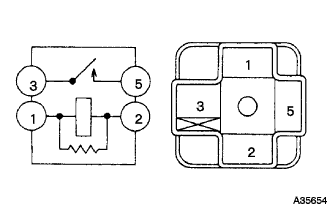 |
Remove the VVT LH relay or VVT RH relay from the engine room No. 2 relay block.
Measure the resistance according to the value(s) in the table below.
| Tester Connection | Condition | Specified Condition |
| 3 - 5 | When no battery voltage applied to terminals 1 and 2 | 10 kΩ or higher |
| 3 - 5 | When battery voltage applied to terminals 1 and 2 | Below 1 Ω |
|
| ||||
| OK | |
| 2.CHECK HARNESS AND CONNECTOR (POWER SOURCE VOLTAGE) |
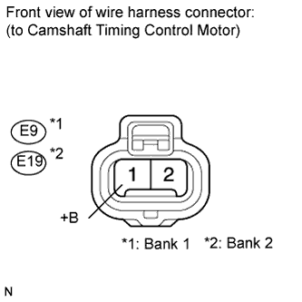 |
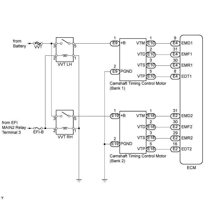
Disconnect the E9 or E19 camshaft timing control motor.
Turn the engine switch on (IG).
Measure the voltage according to the value(s) in the table below.
| Tester Connection | Switch Condition | Specified Condition |
| E9-1 (+B) - Body ground | Engine switch on (IG) | 11 to 14 V |
| E19-1 (+B) - Body ground |
|
| ||||
| OK | |
| 3.CHECK HARNESS AND CONNECTOR |
 |
Turn the engine switch off.
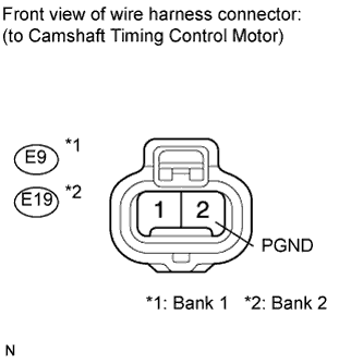
Disconnect the E9 or E19 camshaft timing control motor.
Measure the resistance according to the value(s) in the table below.
| Tester Connection | Condition | Specified Condition |
| E9-2 (PGND) - Body ground | Always | Below 1 Ω |
| E19-2 (PGND) - Body ground |
|
| ||||
| OK | |
| 4.CHECK HARNESS AND CONNECTOR (CAMSHAFT TIMING CONTROL MOTOR - ECM) |
 |
Disconnect the E4 or E2 ECM connector.
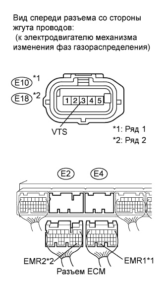
Disconnect the E10 or E18 camshaft timing control motor connector.
| Tester Connection | Condition | Specified Condition |
| E10-3 (VTS) - E4-30 (EMR1) | Always | Below 1 Ω |
| E18-3 (VTS) - E2-29 (EMR2) |
| Tester Connection | Condition | Specified Condition |
| E10-3 (VTS) or E4-30 (EMR1) - Body ground | Always | 10 kΩ or higher |
| E18-3 (VTS) or E2-29 (EMR2) - Body ground |
|
| ||||
| OK | |
| 5.REPLACE CAMSHAFT TIMING CONTROL MOTOR (BANK 1 OR BANK 2) |
Replace the camshaft timing control motor (see page Нажмите здесь).
| NEXT | |
| 6.CONFIRM WHETHER MALFUNCTION HAS BEEN SUCCESSFULLY REPAIRED |
Connect the intelligent tester to the DLC3.
Turn the engine switch on (IG).
Turn the tester ON.
Clear the DTCs (see page Нажмите здесь).
Start the engine and allow the engine idle for 10 seconds or more.
Enter the following menus: Powertrain / Engine / DTC.
Read DTCs.
| Display (DTC Output) | Proceed to |
| No DTC | A |
| Other DTCs | B |
|
| ||||
| A | ||
| ||
| 7.INSPECT CAMSHAFT TIMING CONTROL MOTOR (BANK 1 OR BANK 2) |
Check that the 3 bolts of the camshaft timing control motor are tightened securely.
|
| ||||
| OK | |
| 8.REPAIR OR REPLACE HARNESS OR CONNECTOR (CAMSHAFT TIMING CONTROL MOTOR - VVT LH OR VVT RH RELAY) |
| NEXT | |
| 9.CONFIRM WHETHER MALFUNCTION HAS BEEN SUCCESSFULLY REPAIRED |
Connect the intelligent tester to the DLC3.
Turn the engine switch on (IG).
Turn the tester ON.
Clear the DTCs (see page Нажмите здесь).
Start the engine and allow the engine idle for 10 seconds or more.
Enter the following menus: Powertrain / Engine / DTC.
Read DTCs.
| Display (DTC Output) | Proceed to |
| No DTC | A |
| Other DTCs | B |
|
| ||||
| A | ||
| ||
