ПОДОГРЕВАЕМЫЙ КИСЛОРОДНЫЙ ДАТЧИК (датчик 1) > УСТАНОВКА |
| 1. INSTALL HEATED OXYGEN SENSOR (for Bank 1) |
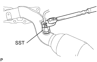 |
Using SST, remove the heated oxygen sensor from the exhaust manifold LH.
| 2. INSTALL HEATED OXYGEN SENSOR (for Bank 2) |
 |
Using SST, remove the heated oxygen sensor from the exhaust manifold RH.
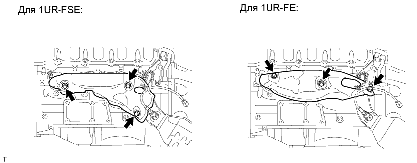
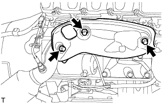
| 3. INSTALL NO. 2 EXHAUST MANIFOLD HEAT INSULATOR |
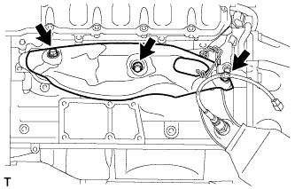 |
Install the heat insulator with the 3 bolts.
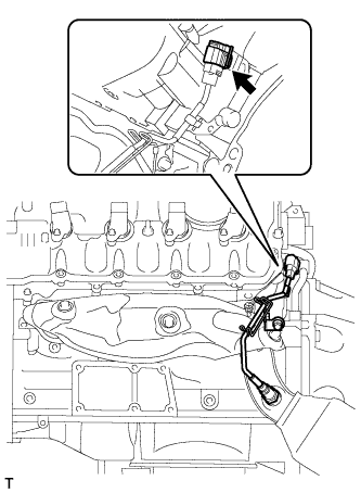 |
Connect the sensor connector.
| 4. INSTALL EXHAUST MANIFOLD SUB-ASSEMBLY LH |
Установите новую прокладку.
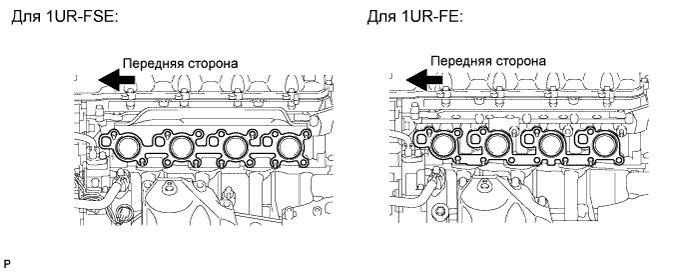
Установите выпускной коллектор на головку блока цилиндров и закрепите его 8 гайками, затягивая их в последовательности, показанной на рисунке.
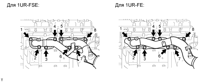
Установите теплозащитный экран и закрепите его 3 болтами.
Подсоедините разъем датчика.
| 5. INSTALL NO. 1 EXHAUST MANIFOLD HEAT INSULATOR |
 |
Install the heat insulator with the 3 bolts.
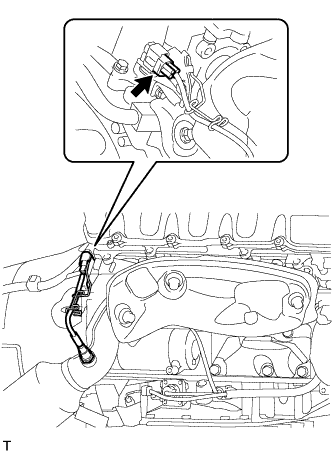 |
Connect the sensor connector.
| 6. INSTALL EXHAUST MANIFOLD SUB-ASSEMBLY RH |
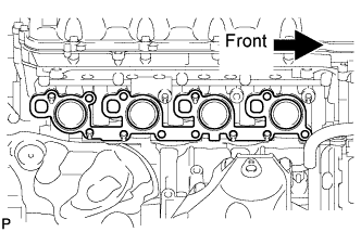 |
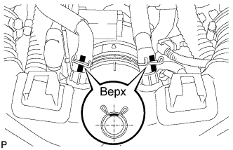
Install a new gasket as shown in the illustration.
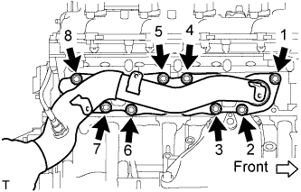 |
Install the exhaust manifold to the cylinder head with the new 8 nuts in the order shown in the illustration.
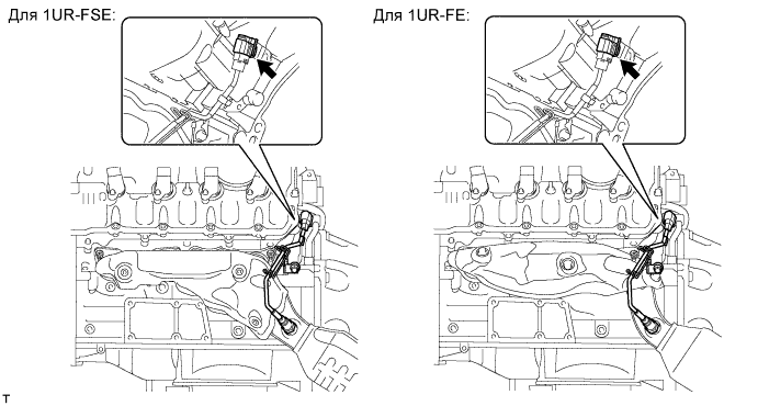
| 7. INSTALL OIL DIPSTICK GUIDE |
Apply a light coat of engine oil to a new O-ring.
Install the new O-ring to the guide.
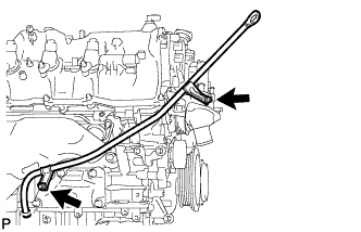 |
Install the dipstick guide with the 2 bolts.
Install the dipstick.
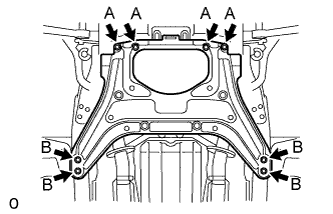
| 8. INSTALL FRONT SUSPENSION MEMBER REINFORCEMENT LH |
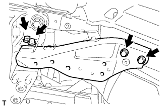 |
Установите правое усиление элемента передней подвески на автомобиль и закрепите его 4 болтами.
| 9. INSTALL FRONT SUSPENSION MEMBER REINFORCEMENT RH |
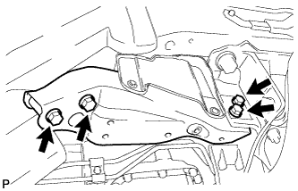 |
Установите правое усиление элемента передней подвески на автомобиль и закрепите его 4 болтами.
| 10. INSTALL ENGINE UNDER COVER SUB-ASSEMBLY LH |
| 11. INSTALL ENGINE UNDER COVER SUB-ASSEMBLY RH |
| 12. CONNECT FRONT STABILIZER BAR |
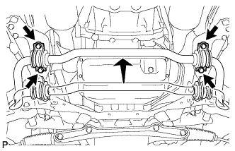 |
Подсоедините штангу стабилизатора к задней скобе и закрепите ее 4 болтами.
| 13. INSTALL ENGINE UNDER COVER REAR LH |
| 14. INSTALL ENGINE UNDER COVER REAR RH |
| 15. INSTALL NO. 2 STEERING INTERMEDIATE SHAFT ASSEMBLY (w/ VGRS) |
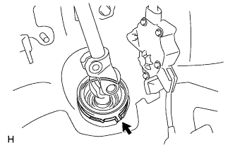 |
Установите зажим на чехол выходного отверстия рулевой колонки.
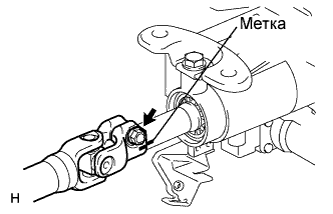 |
Совместите метки на промежуточном вале рулевого управления № 2 в сборе и рулевой колонке.
Вверните болт.
| 16. INSTALL NO. 2 STEERING INTERMEDIATE SHAFT ASSEMBLY (w/o VGRS) |
|
Установите зажим на чехол выходного отверстия рулевой колонки.
|
Совместите метки на промежуточном вале рулевого управления № 2 в сборе и главном вале рулевого управления.
Вверните болт.
| 17. INSTALL STEERING INTERMEDIATE SHAFT (w/o VGRS) |
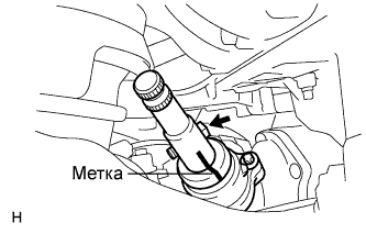 |
Совместите метки на промежуточном вале рулевого управления в сборе и тяге рулевого управления с усилителем.
Вверните болт.
| 18. INSTALL STEERING SLIDING YOKE WITH SHAFT SUB-ASSEMBLY (w/ VGRS) |
 |
Совместите метки на промежуточном вале рулевого управления № 2 в сборе и шлицевом хомуте рулевого вала в сборе.
Совместите метки на шлицевом хомуте рулевого вала в сборе и тяге рулевого управления.
Не затягивая, вверните болт (B).
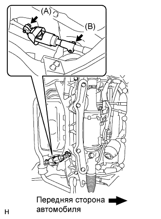 |
Вверните болт (A) и затяните болт (B).
| 19. INSTALL STEERING SLIDING YOKE WITH SHAFT SUB-ASSEMBLY (w/o VGRS) |
|
Совместите метки на промежуточном вале рулевого управления № 2 в сборе и шлицевом хомуте рулевого вала в сборе.
Совместите метки на шлицевом хомуте рулевого вала в сборе и промежуточном вале рулевого управления в сборе.
Не затягивая, вверните болт (B).
|
Вверните болт (A) и затяните болт (B).
| 20. INSTALL FRONT EXHAUST PIPE ASSEMBLY |
Install the front exhaust pipe (see page Нажмите здесь).
| 21. INSTALL GENERATOR |
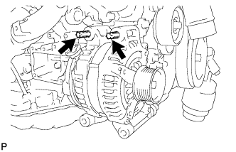 |
Using an E8 "TORX" socket wrench, set the generator with the 2 stud bolts.
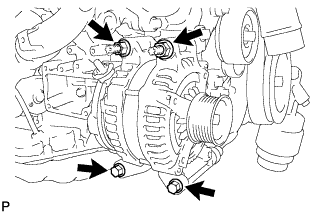 |
Install the generator with the 2 bolts and 2 nuts.
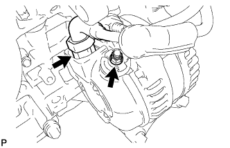 |
Connect the generator connector.
Connect the harness to the +B terminal with the nut.
| 22. INSTALL V-RIBBED BELT |
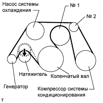 |
Install the V belt as shown in the illustration.
Rotate the tensioner pulley counterclockwise, and then remove the fix bar.
| 23. INSTALL INTAKE AIR CONNECTOR PIPE |
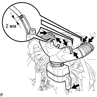 |
Align the protrusion of the intake air resonator with the cutout of the bracket and insert the protrusion.
Install the intake air connector pipe with the 3 hose clamps.
 |
Connect the No. 1 ventilation hose and No. 2 ventilation hose to the intake air connector pipe.
| 24. INSTALL NO. 2 ENGINE UNDER COVER |
 |
Install the under cover with the 8 bolts.
| 25. INSTALL FRONT SUSPENSION MEMBER PROTECTOR LOWER |
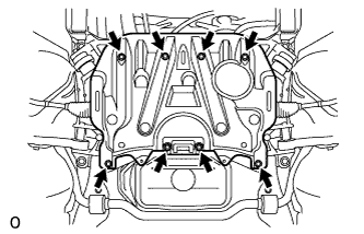 |
Install the suspension member protector with the 8 bolts.
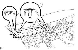
| 26. INSTALL NO. 1 ENGINE UNDER COVER |
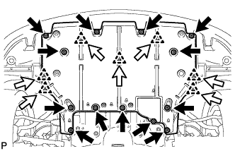 |
Install the cover with the 7 clips and 13 screws.
| 27. INSTALL NO. 1 AIR CLEANER INLET |
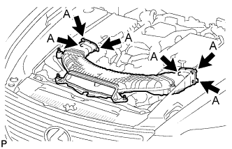 |
Align the holes with the connection areas labeled A, and attach the No. 1 air cleaner inlet.
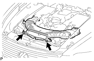 |
Install the No. 1 air cleaner inlet with the 2 bolts.
| 28. INSTALL AIR CLEANER INLET COVER |
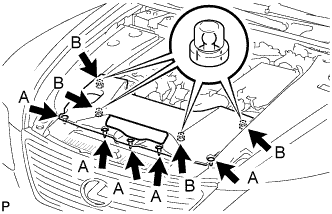 |
Attach the 4 clips B.
Install the air cleaner inlet cover with the 5 clips A.
| 29. INSTALL V-BANK COVER SUB-ASSEMBLY |
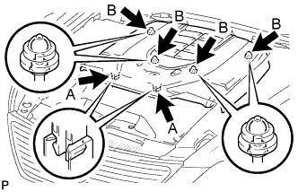 |
After sliding the cover from the vehicle front to the rear to attaching the 2 clips A, attach the 4 clips B and install the V bank cover.
| 30. CONNECT CABLE TO NEGATIVE BATTERY TERMINAL |
| 31. INSTALL COWL TOP VENTILATOR LOUVER RH |
 |
Install the 6 clips and cowl top ventilator louver RH.
| 32. PERFORM INITIALIZATION |
Perform initialization (see page Нажмите здесь).
