НАСОС СИСТЕМЫ ОХЛАЖДЕНИЯ > УСТАНОВКА

для подготовки Нажмите здесь


1. INSTALL WATER PUMP


    A149466E01
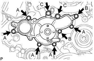
  1. Install the water pump and gasket with the 9 bolts as shown the illustration.

    Момент затяжки: 
    20 Н*м{ 204 кгс*см , 15 фунт-сила-футов } for Bolt A
    23 Н*м{ 235 кгс*см , 17 фунт-сила-футов } for Bolt B
    47 Н*м{ 479 кгс*см , 35 фунт-сила-футов } for Bolt C


2. INSTALL WATER PUMP PULLEY


    A148456E01
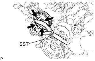
  1. Temporarily install the pulley with the 4 bolts.

  1. Using SST, hold the pulley and tighten the 4 bolts.

    Специальный инструмент (SST):
    09960-10010   (09962-01000, 09963-01000)

    Момент затяжки: 
    21 Н*м{ 214 кгс*см , 15 фунт-сила-футов }


3. INSTALL WATER INLET HOUSING


    A148488
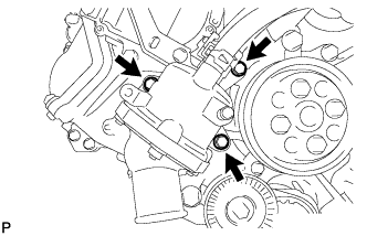
  1. Install a new gasket to the water pump.

  1. Install the water inlet housing with the 3 bolts.

    Момент затяжки: 
    21 Н*м{ 214 кгс*см , 15 фунт-сила-футов }


4. CONNECT NO. 3 WATER BY-PASS HOSE


    A158409E01
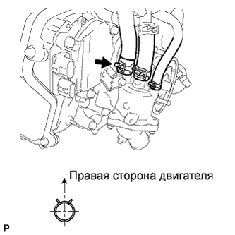
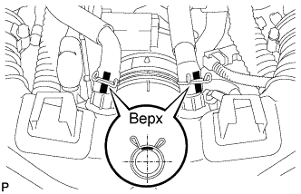
  1. Using needle-nose pliers, grip the claws of the clip and slide the clip to connect the No. 3 water by-pass hose.


5. CONNECT WATER INLET HOSE


    A158409E02
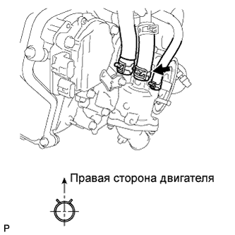
  1. Using needle-nose pliers, grip the claws of the clip and slide the clip to connect the water inlet hose.


6. CONNECT NO. 5 WATER BY-PASS HOSE


    A158410E01
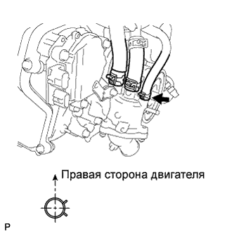
  1. Using needle-nose pliers, grip the claws of the clip and slide the clip to connect the No. 5 water by-pass hose.


7. CONNECT NO. 2 RADIATOR HOSE


8. CONNECT OIL LEVEL DIPSTICK GUIDE


    A149483
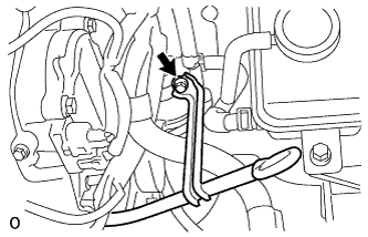
  1. Connect the dipstick guide with the bolt.

    Момент затяжки: 
    10 Н*м{ 102 кгс*см , 7 фунт-сила-футов }


9. INSTALL V-RIBBED BELT


    A149057E01
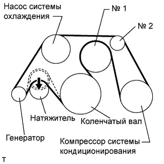
  1. Install the V belt as shown in the illustration.

    ПРИМЕЧАНИЕ:
    Check that the drive belt is properly set to each pulley.


    1. Rotate the tensioner pulley counterclockwise, and then remove the fix bar.


10. INSTALL INTAKE AIR CONNECTOR PIPE


A148828E01
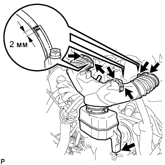
  1. Align the protrusion of the intake air resonator with the cutout of the bracket and insert the protrusion.

  1. Install the intake air connector pipe with the 3 hose clamps.

    Момент затяжки: 
    4.8 Н*м{ 48 кгс*см , 42 фунт-сила-дюймов } for intake air connector pipe and throttle body
    3.8 Н*м{ 38 кгс*см , 34 фунт-сила-дюймов } for intake air connector pipe and intake air resonator

    ПРИМЕЧАНИЕ:
    Insert the protrusion of the intake air connector pipe into the hole of the hose clamp.

    УКАЗАНИЕ:
    1. The intake air connector pipe and throttle body can be tightened within the range of 4.0 N*m (41 kgf*cm. 35 in.*lbf) to 5.5 N*m (56 kgf*cm. 49 in.*lbf), and the intake air connector pipe and air cleaner assembly can be tightened within the range of 2.0 N*m (20 kgf*cm. 18 in.*lbf) to 5.5 N*m (56 kgf*cm. 49 in.*lbf).
    2. When tightening the hose clamp, make sure the hose clamp's end is within the painted white line (width: 2 mm).


    A148829E01
  1. Connect the No. 1 ventilation hose and No. 2 ventilation hose to the intake air connector pipe.

    ПРИМЕЧАНИЕ:
    1. Position the claws of the clamps as shown in the illustration.
    2. Install the clips so that they are within the hose's paint marks.


11. INSTALL RADIATOR RESERVOIR ASSEMBLY
  1. Install the radiator reservoir with the 2 bolts.

    Момент затяжки: 
    5.0 Н*м{ 51 кгс*см , 44 фунт-сила-дюймов }


    A132831E01
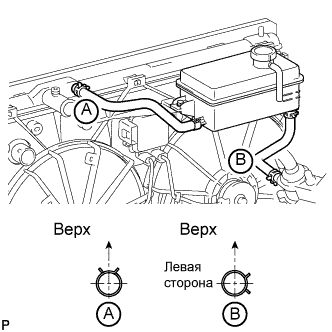
  1. Connect the 2 reservoir hoses.

    УКАЗАНИЕ:
    The direction of the hose clamp is indicated in the illustration.


12. INSTALL NO. 1 AIR CLEANER INLET


A158334E01
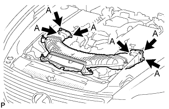
  1. Align the holes with the connection areas labeled A, and attach the No. 1 air cleaner inlet.


    A148822
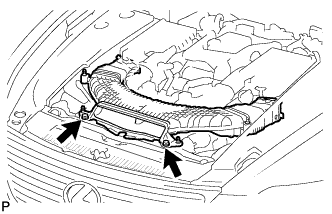
  1. Install the No. 1 air cleaner inlet with the 2 bolts.

    Момент затяжки: 
    5.0 Н*м{ 51 кгс*см , 44 фунт-сила-дюймов }


13. INSTALL ENGINE ROOM SIDE COVER RH


    A149480
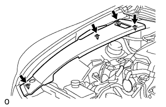
  1. Install the side cover with the 4 clips.


14. INSTALL AIR CLEANER INLET COVER SUB-ASSEMBLY


A148821E01
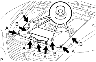
  1. Attach the 4 clips B.

    ПРИМЕЧАНИЕ:
    1. Make sure the clips are attached securely.
    2. Attaching the clips forcefully or hitting the top of the clips may damage them.

  1. Install the air cleaner inlet cover with the 5 clips A.


15. INSTALL V-BANK COVER SUB-ASSEMBLY


A148820E01
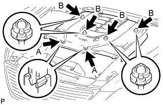
  1. After sliding the cover from the vehicle front to the rear to attaching the 2 clips A, attach the 4 clips B and install the V bank cover.

    ПРИМЕЧАНИЕ:
    1. Make sure the clips are attached securely.
    2. Attaching the clips forcefully or hitting the top of the clips may damage them.


16. ADD ENGINE COOLANT

ПРИМЕЧАНИЕ:
Before adding coolant, turn the A/C switch OFF.

Total capacity:
11.8 liters (12.5 US qts, 10.4 Imp. qts)

  1. Tighten the radiator drain cock plug and 2 cylinder block drain cock plugs.

    Момент затяжки: 
    13 Н*м{ 133 кгс*см , 10 фунт-сила-футов } for cylinder block drain cock plug

  1. Add TOYOTA Super Long Life Coolant (SLLC) into the radiator reservoir.

    Capacity:
    Approximately 5.0 liters (5.3 US qts, 4.4 Imp. qts)

    УКАЗАНИЕ:
    1. TOYOTA vehicles are filled with TOYOTA SLLC at the factory. In order to avoid damage to the engine cooling system and other technical problems, only use TOYOTA SLLC or similar high quality ethylene glycol based non-silicate, non-amine, non-nitrite, non-borate coolant with long-life hybrid organic acid technology (coolant with long-life hybrid organic acid technology consists of a combination of low phosphates and organic acids).
    2. Please contact any authorized Toyota dealer, or repairer or another duly qualified and equipped professional for further details.
    3. The thermostat open timing can be confirmed by pressing the inlet radiator hose by hand, and checking when the coolant starts to flow inside the hose.


    A140930
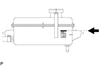
  1. Further add coolant into the reservoir until it reaches the FULL line.

  1. Press the No. 1 and No. 2 radiator hoses several times by hand, and then check the coolant level.
    If the coolant level is low, add coolant.


    A132825E01
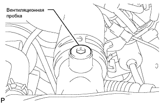
  1. Using a 6 mm hexagon wrench, install the vent plug.

    Момент затяжки: 
    1.5 Н*м{ 15 кгс*см , 13 фунт-сила-дюймов }


  1. Bleed air from the cooling system.

    ПРИМЕЧАНИЕ:
    Before starting the engine to warm up the engine, turn the A/C switch OFF.


    1. While idling the engine for approximately 10 minutes, make sure the coolant remains at the FULL line by adding coolant as necessary.


    2. A147208E01
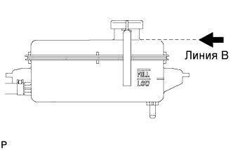
    3. After idling the engine for 10 minutes, add coolant until it reaches the B line at the base of the reservoir's filler neck.

      Capacity:
      Approximately 2.5 to 3.5 liters (2.6 to 3.7 US qts, 2.2 to 3.1 Imp. qts)

      УКАЗАНИЕ:
      The B line is the lower edge of the inner wall of the filler neck.

    4. Close the radiator reservoir cap, and run the engine at 1500 to 2000 rpm for 5 minutes.

      УКАЗАНИЕ:
      The thermostat open timing can be confirmed by pressing the No. 1 radiator hose by hand, and checking when the SLLC starts to flow inside the hose.

      ПРЕДОСТЕРЕЖЕНИЕ:
      When pressing the radiator hose:
      1. Wear protective gloves.
      2. Be careful as the radiator hose is hot.
      3. Keep your hands away from the radiator fan.

  1. Stop the engine and wait until the coolant cools down to ambient temperature.

    ПРЕДОСТЕРЕЖЕНИЕ:
    Do not remove the radiator reservoir cap while the engine and radiator are still hot. Pressurized, hot coolant and steam may be released and cause serious burns.


    A140930
  1. Check the coolant level.
    If the coolant level is below the FULL line, add coolant until it reaches the FULL line.


17. INSPECT FOR COOLANT LEAK

ПРИМЕЧАНИЕ:
Before each inspection, turn the A/C switch OFF.

ПРЕДОСТЕРЕЖЕНИЕ:
Do not remove the radiator reservoir cap while the engine and radiator are still hot. Pressurized, hot engine coolant and steam may be released and cause serious burns.


    A148610
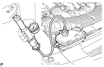
  1. Fill the radiator with coolant and attach a radiator cap tester.

  1. Warm up the engine.

  1. Using the radiator cap tester, increase the pressure inside the radiator to 118 kPa (1.2 kgf/cm2, 17 psi), and check that the pressure does not drop.
    If the pressure drops, check the hoses, radiator and water pump for leaks. If no external leaks are found, check the heater core, cylinder block and head.


18. INSTALL NO. 1 ENGINE UNDER COVER


    A132845
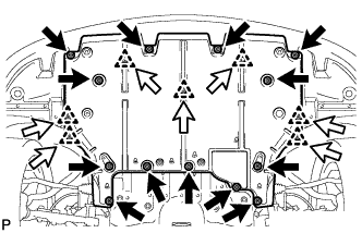
  1. Install the cover with the 7 clips and 13 screws.