МАСЛЯНЫЙ НАСОС > СНЯТИЕ |
| 1. DISCHARGE FUEL SYSTEM PRESSURE |
Discharge fuel system pressure (see page Нажмите здесь).
| 2. REMOVE COWL TOP VENTILATOR LOUVER RH |
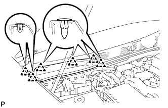 |
Remove the 6 clips and cowl top ventilator louver RH.
| 3. DISCONNECT CABLE FROM NEGATIVE BATTERY TERMINAL |
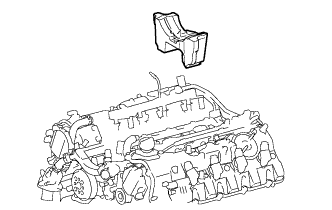
| 4. REMOVE V-BANK COVER SUB-ASSEMBLY |
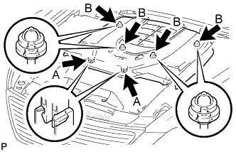 |
While using both hands, lift the rear side of the cover upwards to detach the 4 clips B. Slide the cover towards the front of the vehicle to detach the 2 clips labeled A, and remove the V-bank cover.
| 5. REMOVE AIR CLEANER INLET COVER SUB-ASSEMBLY |
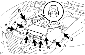 |
Remove the 5 clips A.
Lift up the air cleaner inlet cover to detach the 4 clips B, and remove the cover.
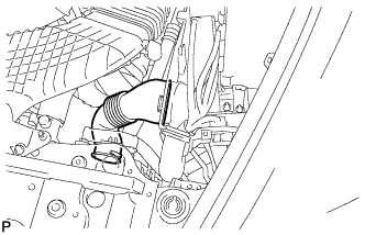
| 6. REMOVE NO. 1 AIR CLEANER INLET |
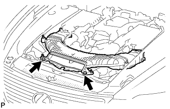 |
Remove the 2 bolts.
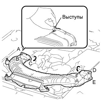 |
Hold the air cleaner inlet by the protrusions A and B, and detach the connections.
Rotate the No. 1 air cleaner inlet as shown in the illustration to detach the protrusion C.
Hold the air cleaner inlet by the protrusions D and E, and detach the connections.
Rotate the No. 1 air cleaner inlet as shown in the illustration to detach the protrusion F.
| 7. REMOVE ENGINE ROOM SIDE COVER LH |
 |
Remove the 4 clips and engine room side cover.
| 8. REMOVE ENGINE ROOM SIDE COVER RH |
 |
Remove the 4 clips and engine room side cover.
| 9. REMOVE BATTERY CLAMP SUB-ASSEMBLY |
Remove the nut, battery clamp and 2 clamp bolts.
| 10. REMOVE BATTERY TRAY |
Remove the battery insulator and battery.
Remove the 3 bolts and battery tray.
| 11. REMOVE NO. 1 ENGINE UNDER COVER |
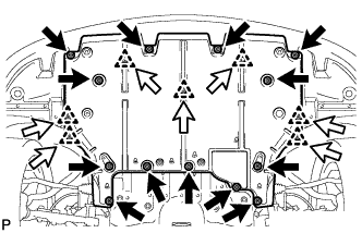 |
Remove the 13 screws, 7 clips and cover.
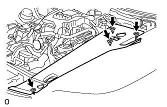
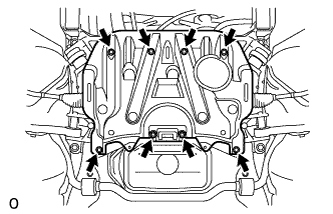
| 12. REMOVE NO. 2 ENGINE UNDER COVER |
 |
Remove the 8 bolts and under cover.
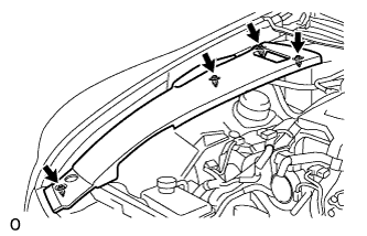
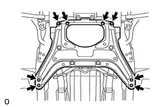
| 13. REMOVE FRONT SUSPENSION MEMBER PROTECTOR LOWER |
 |
Remove the 8 bolts and suspension member protector.
| 14. REMOVE ENGINE UNDER COVER REAR LH |
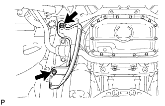 |
Выверните 2 винта и снимите левую заднюю защиту картера двигателя.
| 15. REMOVE ENGINE UNDER COVER REAR RH |
| 16. DRAIN ENGINE OIL |
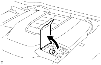 |
Open the oil filler cap service hole cover.
Remove the oil filler cap.
Remove the oil pan drain plug and drain the engine oil into a container.
Install a new gasket and the oil pan drain plug.
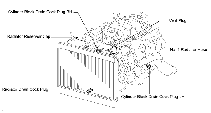
| 17. DRAIN ENGINE COOLANT |
Loosen the radiator drain cock plug.
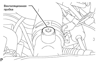 |
Remove the radiator reservoir cap, and using a 6 mm hexagon wrench, remove the vent plug.
Drain coolant.
Loosen the 2 cylinder block drain cock plugs.
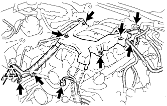
| 18. REMOVE INTAKE AIR CONNECTOR PIPE |
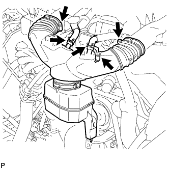 |
Disconnect the No. 1 ventilation hose and No. 2 ventilation hose from the intake air connector pipe.
Loosen the 3 hose clamps, and remove the intake air connector pipe.
| 19. REMOVE AIR CLEANER ASSEMBLY RH |
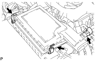 |
Disconnect the MAF meter connector.
Disconnect the 2 clamps and air cleaner cap.
Remove the air cleaner element from air cleaner case.
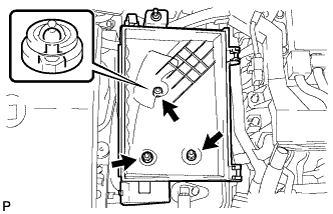 |
Remove the 2 nuts, clip and air cleaner case.
| 20. REMOVE AIR CLEANER ASSEMBLY LH |
 |
Disconnect the MAF meter connector.
Disconnect the 2 clamps and air cleaner cap.
Remove the air cleaner element from air cleaner case.
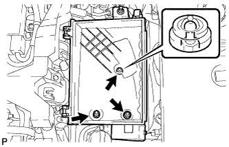 |
Remove the 2 nuts, clip and air cleaner case.
| 21. REMOVE RADIATOR RESERVOIR ASSEMBLY |
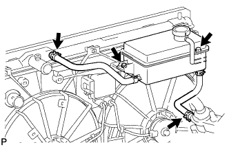 |
Disconnect the 2 reservoir hoses.
Remove the 2 bolts and reservoir.
| 22. REMOVE V-RIBBED BELT |
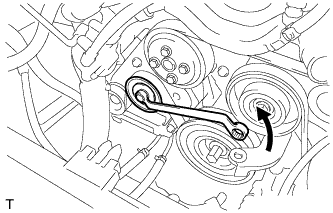 |
Rotate the tensioner pulley counterclockwise to loosen the belt tension.
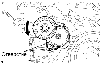 |
While turning the belt tensioner counterclockwise, align the holes. Insert a bar of φ5 mm (0.20 in.) into the holes to fix the belt tensioner in place.
Remove the V belt.
| 23. DISCONNECT NO. 1 RADIATOR HOSE |
| 24. DISCONNECT NO. 2 RADIATOR HOSE |
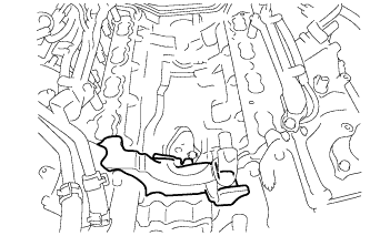
| 25. REMOVE ENGINE ROOM ECU OUTLET DUCT |
 |
Remove the outlet duct.
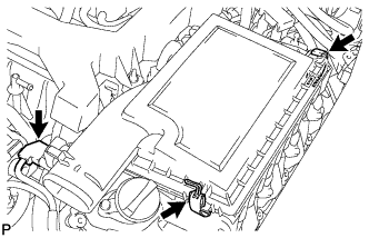
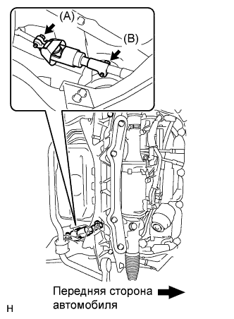
| 26. REMOVE SKID CONTROL ECU |
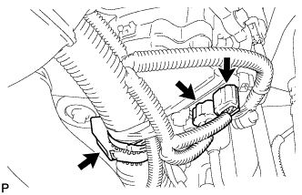
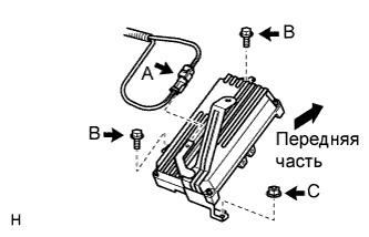 |
Отсоедините короткозамыкатель имитатора хода педали тормоза (A) от кронштейна ЭБУ системы противоскольжения.
Выверните 2 болта (B), отверните гайку (C) и снимите ЭБУ.
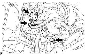
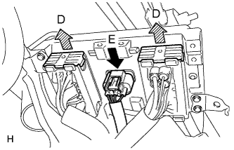 |
Поднимите 2 рычага блокировки вверх, чтобы освободить замки, и отсоедините 2 разъема (D).
Отсоедините разъем (E).
| 27. REMOVE SKID CONTROL ECU BRACKET |
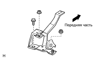 |
Отверните 2 гайки, выверните болт и снимите кронштейн.
| 28. DISCONNECT ENGINE WIRE |
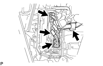
for Engine Room LH Side:
 |
Remove the ECM box cover (upper).
Disconnect the 3 ECT connectors and 4 ECM connectors from the ECM box.
 |
Disconnect the camshaft timing control valve connector.
Disconnect the 4 ignition coil connectors.
Disconnect the 2 VVT sensor connectors.
Disconnect the No. 8 engine wire connector.
Remove the 2 bolts and disconnect the clamp and 2 clamp brackets.
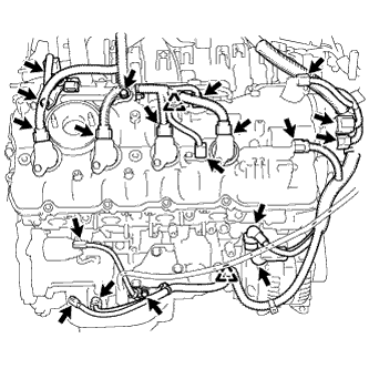
 |
Disconnect the engine coolant temperature sensor connector.
Disconnect the engine oil pressure sensor connector.
Disconnect the 2 camshaft timing control motor connectors. (for Bank 1)
Detach the clamp and disconnect the cooler compressor connector.
Remove the 3 bolts and disconnect the 3 clamps and ground wire.
Remove the bolt and clamp bracket.
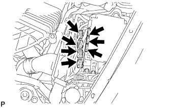
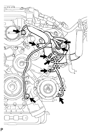
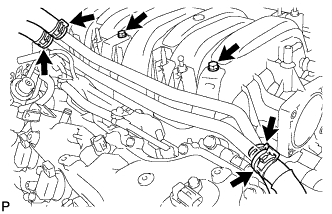
for Engine Room RH Side:
 |
Detach the clamp and disconnect the 3 connectors with front controller.
 |
Remove the 2 nuts and disconnect the wires with No. 1 engine room junction block.
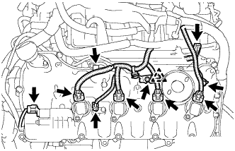
 |
Disconnect the camshaft timing control valve connector.
Disconnect the 4 ignition coil connectors.
Disconnect the 2 VVT sensor connectors.
Disconnect the engine wire connector.
Disconnect the 2 camshaft timing control motor connectors. (for Bank 2)
Disconnect the camshaft position sensor connector.
Remove the nut and disconnect the generator wire and connector.
Remove the nut and disconnect the starter wire and connector.
Disconnect the crankshaft position sensor connector.
Disconnect the engine oil level sensor connector.
Remove the 3 bolts, and disconnect the 3 clamp brackets and 2 clamps.
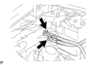
 |
Remove the bolt and disconnect the ground wire.
 |
Disconnect the No. 1 vacuum switching valve connector.
Disconnect the intake air control valve actuator connector.
Remove the 2 bolts and disconnect the 2 clamp brackets and clamp.
Remove the 4 nuts and disconnect the engine wire.
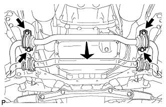
| 29. REMOVE FRONT EXHAUST PIPE ASSEMBLY |
Remove the front exhaust pipe (see page Нажмите здесь).
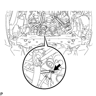
| 30. DISCONNECT FRONT STABILIZER BAR |
 |
Выверните 4 болта и отсоедините штангу стабилизатора от задней скобы.
| 31. REMOVE FRONT SUSPENSION MEMBER REINFORCEMENT LH |
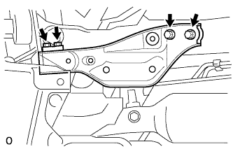 |
Выверните 4 болта и снимите левое усиление элемента передней подвески с автомобиля.
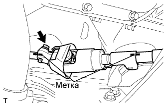
| 32. REMOVE STEERING SLIDING YOKE WITH SHAFT SUB-ASSEMBLY (w/ VGRS) |
 |
Ослабьте болт (A), выверните болт (B), а затем сдвиньте шлицевой хомут рулевого вала вместе с валом.
 |
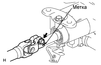
Нанесите метки на шлицевой хомут рулевого вала, промежуточный вал № 2 рулевого управления и тягу рулевого управления.
Выверните болт и снимите шлицевой хомут рулевого вала с промежуточного вала № 2 рулевого управления.
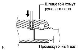 |
Отсоедините вал шлицевого хомута от тяги рулевого управления.
| 33. REMOVE STEERING SLIDING YOKE WITH SHAFT SUB-ASSEMBLY (w/o VGRS) |
|
Ослабьте болт (A), выверните болт (B), а затем сдвиньте шлицевой хомут рулевого вала.
|
Нанесите метки на шлицевой хомут рулевого вала, промежуточный вал № 2 рулевого управления и тягу рулевого управления.
Выверните болт и снимите шлицевой хомут рулевого вала с промежуточного вала № 2 рулевого управления.
|
Отсоедините шлицевой хомут рулевого вала от промежуточного вала рулевого управления.
| 34. REMOVE NO. 2 STEERING INTERMEDIATE SHAFT ASSEMBLY (w/ VGRS) |
 |
Нанесите метки на промежуточный вал № 2 рулевого управления и рулевую колонку.
Выверните болт.
 |
Снимите зажим и промежуточный вал № 2 рулевого управления.
| 35. REMOVE NO. 2 STEERING INTERMEDIATE SHAFT ASSEMBLY (w/o VGRS) |
|
Нанесите метки на промежуточный вал № 2 рулевого управления и рулевую колонку.
Выверните болт.
|
Снимите зажим и промежуточный вал № 2 рулевого управления.
| 36. REMOVE NO. 2 EXHAUST MANIFOLD HEAT INSULATOR |
 |
Disconnect the sensor connector.
 |
Remove the 3 bolts and heat insulator.
| 37. REMOVE EXHAUST MANIFOLD SUB-ASSEMBLY (for Bank 1) |
 |
Remove the 8 nuts, exhaust manifold and gasket.
| 38. DISCONNECT COOLER COMPRESSOR ASSEMBLY |
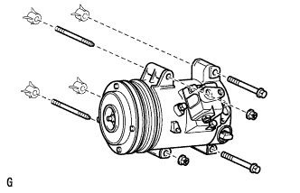 |
Remove the 2 bolts, 2 nuts, 2 stud bolts and disconnect the cooler compressor.
| 39. REMOVE OIL LEVEL DIPSTICK GUIDE |
 |
Remove the dipstick.
Remove the 2 bolts and dipstick guide.
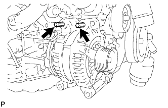
| 40. REMOVE GENERATOR ASSEMBLY |
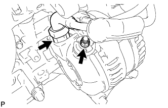 |
Remove the nut, and disconnect the harness from the +B terminal.
Disconnect the generator connector.
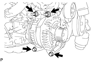 |
Remove the 2 bolts and 2 nuts.
 |
Using an E8 "TORX" socket wrench, remove the 2 stud bolts and generator.
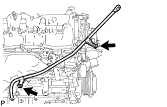
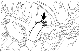
| 41. REMOVE WATER BY-PASS PIPE SUB-ASSEMBLY |
 |
Slide the 4 clamps, and disconnect the heater water inlet hose, heater water outlet hose, water inlet hose, and No. 3 water by-pass hose from the water by-pass pipe sub-assembly.
Remove the 2 bolts and water by-pass pipe.
| 42. REMOVE INTAKE MANIFOLD |
 |
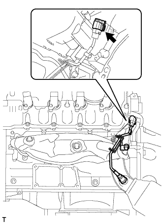
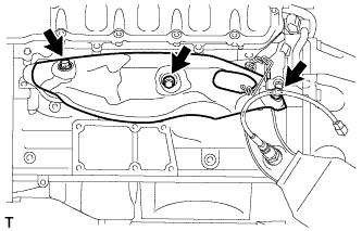
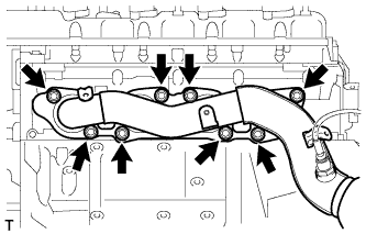
Disconnect the No. 1 ventilation hose from the intake manifold.
 |
Remove the 8 bolts, 2 nuts and intake manifold.
Remove the 2 gaskets from the intake manifold.
| 43. REMOVE NO. 3 ENGINE COVER |
 |
Remove the No. 3 engine cover.
| 44. REMOVE NO. 2 ENGINE COVER SUB-ASSEMBLY LH |
 |
Remove the No. 2 engine cover sub-assembly LH .
| 45. REMOVE WATER INLET HOUSING |
 |
Using needle-nose pliers, grip the claws of the clips and slide the clips to disconnect the water by-pass hoses and water inlet hose.
 |
Remove the 3 bolts, water inlet housing and gasket.
| 46. REMOVE WATER PUMP PULLEY |
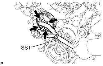 |
Using SST, hold the water pump pulley.
Remove the 4 bolts and water pump pulley.
| 47. REMOVE NO. 2 IDLER PULLEY SUB-ASSEMBLY |
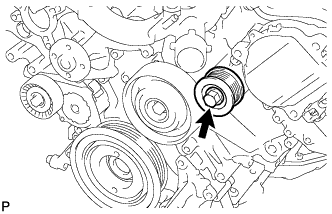 |
Remove the bolt and idler pulley.
| 48. REMOVE NO. 1 IDLER PULLEY SUB-ASSEMBLY |
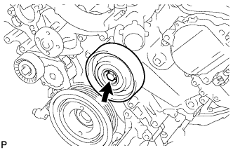 |
Remove the bolt and idler pulley.
| 49. REMOVE FRONT WATER BY-PASS JOINT |
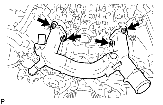 |
Remove the 4 nuts, water by-pass joint and 2 gaskets.
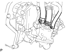
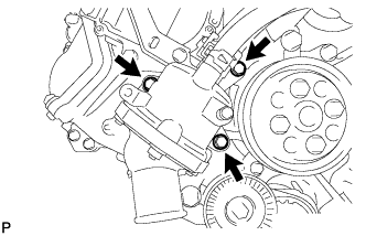
| 50. REMOVE CAMSHAFT TIMING CONTROL MOTOR ASSEMBLY (for Bank 1) |
 |
Disconnect the 2 camshaft timing control motor connectors and engine wire clamp.
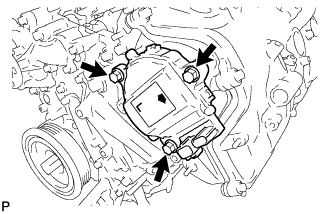 |
Remove the 3 bolts and camshaft timing control motor.
Remove the O-ring from the timing chain cover.
| 51. REMOVE CAMSHAFT TIMING CONTROL MOTOR ASSEMBLY (for Bank 2) |
 |
Disconnect the 2 camshaft timing control motor connectors.
Remove the bolt and engine wire bracket.
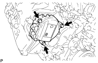 |
Remove the 3 bolts and camshaft timing control motor.
Remove the O-ring from the timing chain cover.
| 52. REMOVE OIL FILTER ELEMENT |
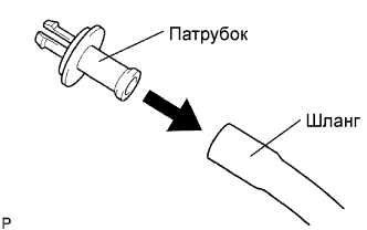 |
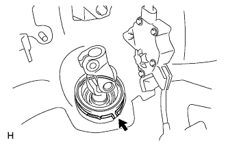
Connect a hose with an inside diameter of 15 mm (0.59 in.) to the pipe.
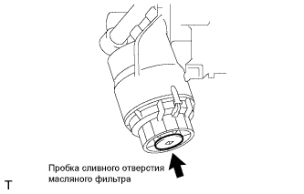 |
Remove the oil filter drain plug.
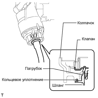 |
Install the pipe to the oil filter cap.
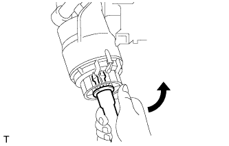 |
Check that oil is drained from the oil filter. Then disconnect the pipe and remove the O-ring, as shown in the illustration.
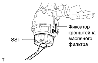 |
Using SST, remove the oil filter cap.
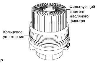 |
Remove the oil filter element and O-ring from the oil filter cap.
| 53. REMOVE OIL FILTER BRACKET |
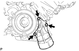 |
Remove the 3 bolts, filter bracket and 2 gaskets.
| 54. REMOVE RESONATOR BRACKET SUB-ASSEMBLY |
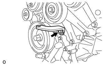 |
Install the resonator bracket with the bolt.
| 55. REMOVE CRANKSHAFT PULLEY |
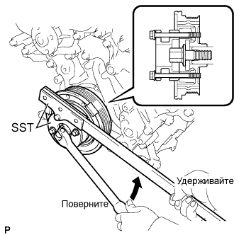 |
Using SST, loosen the crankshaft pulley set bolt.
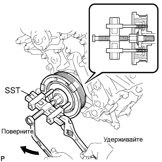 |
Using the pulley set bolt and SST, remove the crankshaft pulley.
| 56. REMOVE IGNITION COIL ASSEMBLY |
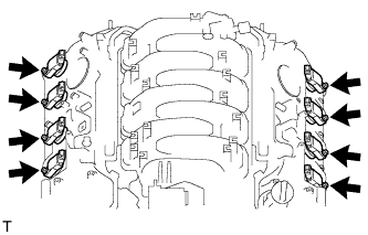 |
Disconnect the 8 ignition coil connectors.
Remove the 8 bolts.
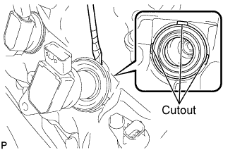 |
Using a screwdriver, pry at the cutouts to remove the 8 ignition coils together with the 8 spark plug tube gaskets.
| 57. REMOVE CYLINDER HEAD COVER SUB-ASSEMBLY (for Bank 1) |
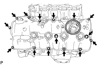 |
Remove the 15 bolts, 2 seal washers, cylinder head cover and gasket.
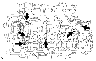 |
Remove the 4 gaskets and 2 O-rings from the camshaft bearing caps (No. 2, No. 3, No. 7).
| 58. REMOVE CYLINDER HEAD COVER SUB-ASSEMBLY (for Bank 2) |
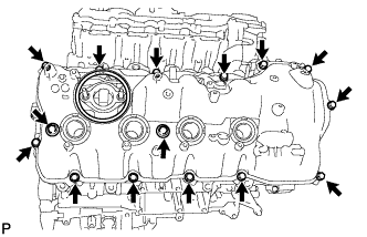 |
Remove the 15 bolts, 2 seal washers, cylinder head cover and gasket.
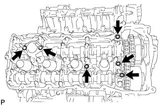 |
Remove the 4 gaskets and 2 O-rings from the camshaft bearing caps (No. 1, No. 3, No. 6).
| 59. REMOVE V-RIBBED BELT TENSIONER ASSEMBLY |
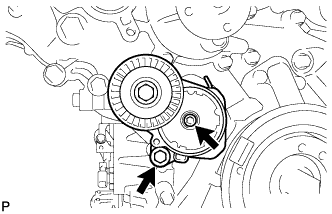 |
Remove the standard bolt, 6 mm hexagon wrench bolt and belt tensioner.
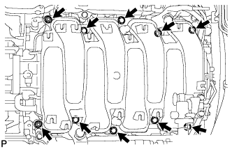
| 60. REMOVE TIMING CHAIN COVER SUB-ASSEMBLY |
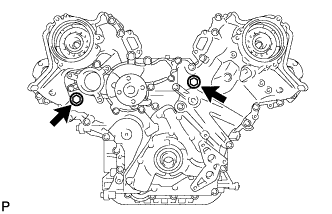 |
Remove the 2 plugs and 2 gaskets.
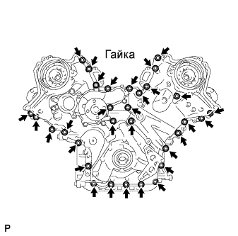 |
Remove the 30 bolts and nut shown in the illustration.
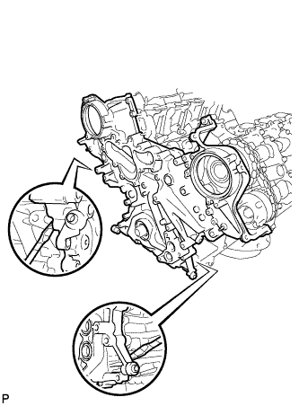 |
Remove the timing chain cover by prying between the timing chain cover and cylinder head and cylinder block with a screwdriver as shown in the illustration.
 |
Remove the oil pump gasket from the cylinder block.
 |
Remove the O-ring from the cylinder block.
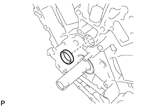
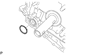
| 61. REMOVE WATER INLET PIPE |
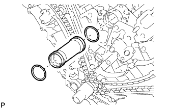 |
Remove the water inlet pipe.
Remove the 2 O-rings from the water inlet pipe.
