ПРОКЛАДКА ГОЛОВКИ БЛОКА ЦИЛИНДРОВ (для ряда 1) > УСТАНОВКА |
| 1. INSPECT CYLINDER HEAD SET BOLT |
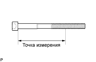 |
Using a vernier caliper, measure the minimum diameter of the elongated thread at the measuring point.
| 2. INSPECT CYLINDER HEAD SUB-ASSEMBLY |
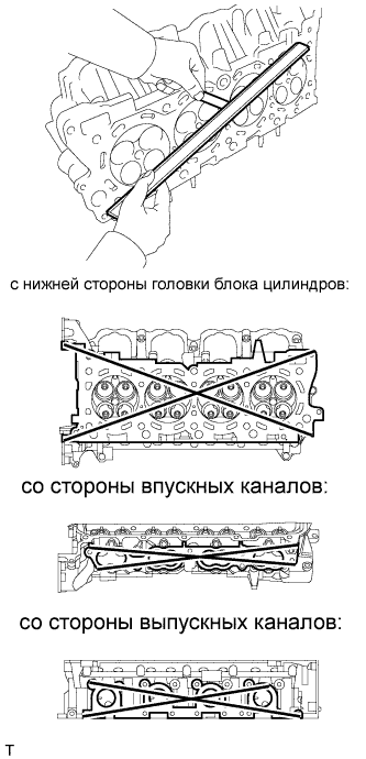 |
Using a precision straightedge and feeler gauge, measure the warpage of the contact surfaces of the cylinder block and manifold.
| Item | Specified Condition |
| Cylinder head lower side | 0.05 mm (0.0020 in.) |
| Intake side | 0.08 mm (0.0031 in.) |
| Exhaust side | 0.05 mm (0.0020 in.) |
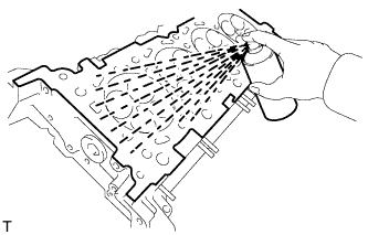 |
Using a dye penetrant, check the intake ports, exhaust ports and cylinder surface for cracks.
If cracked, replace the cylinder head.
| 3. INSTALL CYLINDER HEAD SUB-ASSEMBLY (for Bank 1) |
Check the piston protrusions for each cylinder.
Clean the cylinder block with solvent.
Set the piston of the cylinder to be measured to slightly ATDC.
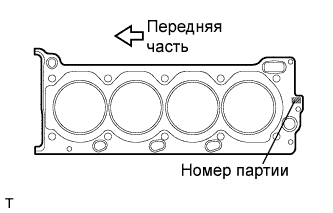 |
Place the cylinder head gasket on the cylinder block surface with the front face of the Lot No. stamp upward.
Place the cylinder head on the cylinder block.
Apply a light coat of engine oil to the threads and under the heads of the cylinder head bolts.
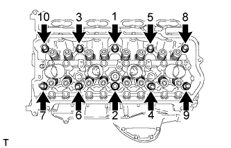 |
Step 1:
Using a 10 mm bi-hexagon wrench, install and uniformly tighten the 10 cylinder head bolts with the plate washers in several steps, in the sequence shown in the illustration.
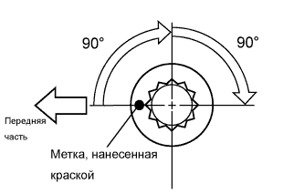 |
Step 2:
Mark the cylinder head bolt head with paint as shown in the illustration.
Tighten the cylinder head bolts another 90° in the sequence shown in step 1.
Step 3:
Tighten the cylinder head bolts by an additional 90° in the sequence shown in step 1.
Check that the painted marks are now facing rearward.
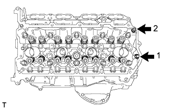 |
Uniformly install the 2 bolts in the sequence shown in the illustration.
| 4. INSTALL VALVE STEM CAP |
Apply a light coat of engine oil to the valve stem caps.
Install the 16 valve stem caps to the cylinder head.
| 5. INSTALL VALVE LASH ADJUSTER ASSEMBLY |
Be sure to inspect the valve lash adjuster before installing it (see page Нажмите здесь).
Install the 16 lash adjusters to the cylinder head.
| 6. INSTALL NO. 1 VALVE ROCKER ARM SUB-ASSEMBLY |
Apply engine oil to the lash adjuster tips and valve stem cap ends.
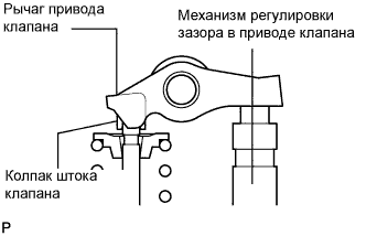 |
Make sure that the 16 valve rocker arms are installed as shown in the illustration.
| 7. INSTALL CAMSHAFT SUB-ASSEMBLY (for Bank 1) |
Install the camshaft (see page Нажмите здесь).
