ПЕРЕДНЯЯ ОПОРА ДВИГАТЕЛЯ > СНЯТИЕ |
| 1. PLACE FRONT WHEELS FACING STRAIGHT AHEAD |
| 2. DISCHARGE FUEL SYSTEM PRESSURE |
Discharge fuel system pressure (see page Нажмите здесь).
| 3. REMOVE COWL TOP VENTILATOR LOUVER RH |
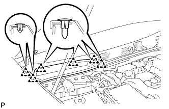 |
Remove the 6 clips and cowl top ventilator louver RH.
| 4. DISCONNECT CABLE FROM NEGATIVE BATTERY TERMINAL |
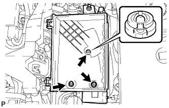
| 5. REMOVE V-BANK COVER SUB-ASSEMBLY |
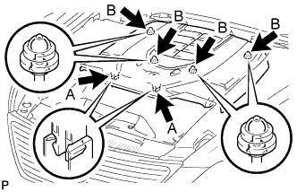 |
While using both hands, lift the rear side of the cover upwards to detach the 4 clips B. Slide the cover towards the front of the vehicle to detach the 2 clips labeled A, and remove the V-bank cover.
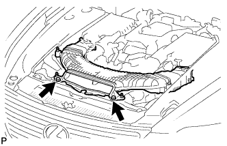
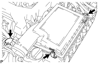
| 6. REMOVE AIR CLEANER INLET COVER SUB-ASSEMBLY |
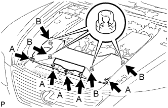 |
Remove the 5 clips A.
Lift up the air cleaner inlet cover to detach the 4 clips B, and remove the cover.
| 7. REMOVE ENGINE ROOM SIDE COVER RH |
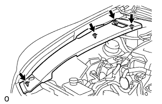 |
Remove the 4 clips and engine room side cover.
| 8. REMOVE ENGINE ROOM SIDE COVER LH |
 |
Remove the 4 clips and engine room side cover.
| 9. REMOVE NO. 1 ENGINE UNDER COVER |
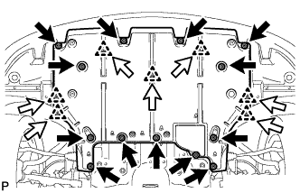 |
Remove the 13 screws, 7 clips and cover.
| 10. REMOVE NO. 2 ENGINE UNDER COVER |
 |
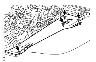
Remove the 8 bolts and under cover.
| 11. REMOVE FRONT SUSPENSION MEMBER PROTECTOR LOWER |
 |
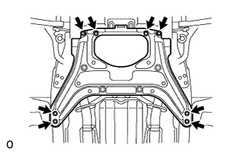
Remove the 8 bolts and suspension member protector.
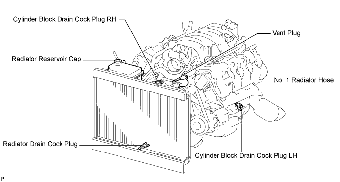
| 12. DRAIN ENGINE COOLANT |
Loosen the radiator drain cock plug.
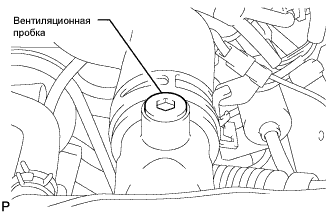 |
Remove the radiator reservoir cap, and using a 6 mm hexagon wrench, remove the vent plug.
Drain coolant.
Loosen the 2 cylinder block drain cock plugs.
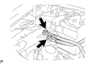
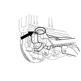
| 13. DISCONNECT NO. 1 OIL COOLER INLET HOSE |
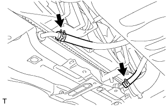 |
Using needle-nose pliers, grip the claws of the clip and slide the clip to disconnect the oil cooler hose.
| 14. DISCONNECT NO. 1 OIL COOLER OUTLET HOSE |
Using needle-nose pliers, grip the claws of the clip and slide the clip to disconnect the oil cooler hose.
| 15. REMOVE FRONT WHEEL |
| 16. REMOVE FRONT BUMPER COVER |
Remove the front bumper cover (see page Нажмите здесь).
| 17. REMOVE FRONT SUSPENSION CROSSMEMBER LOWER |
 |
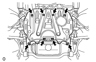
Remove the 6 bolts, 4 nuts and suspension crossmember lower.
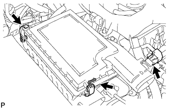
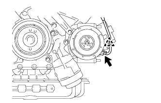
| 18. REMOVE NO. 1 AIR CLEANER INLET |
 |
Remove the 2 bolts.
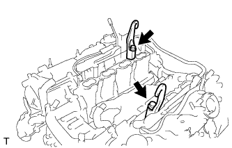
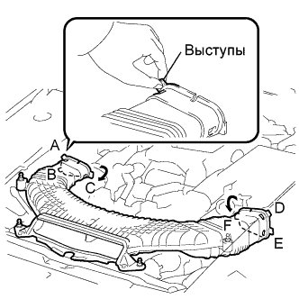 |
Hold the air cleaner inlet by the protrusions A and B, and detach the connections.
Rotate the No. 1 air cleaner inlet as shown in the illustration to detach the protrusion C.
Hold the air cleaner inlet by the protrusions D and E, and detach the connections.
Rotate the No. 1 air cleaner inlet as shown in the illustration to detach the protrusion F.
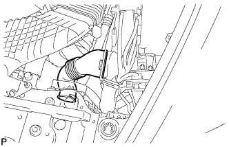
| 19. REMOVE INTAKE AIR CONNECTOR PIPE |
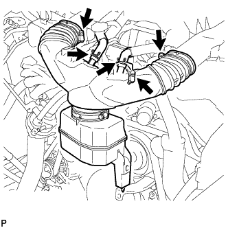 |
Disconnect the No. 1 ventilation hose and No. 2 ventilation hose from the intake air connector pipe.
Loosen the 3 hose clamps, and remove the intake air connector pipe.
| 20. REMOVE V-RIBBED BELT |
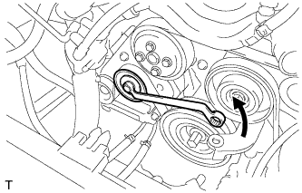 |
Rotate the tensioner pulley counterclockwise to loosen the belt tension.
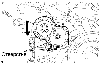 |
While turning the belt tensioner counterclockwise, align the holes. Insert a bar of φ5 mm (0.20 in.) into the holes to fix the belt tensioner in place.
Remove the V belt.
| 21. REMOVE AIR CLEANER ASSEMBLY LH |
 |
Disconnect the MAF meter connector.
Disconnect the 2 clamps and air cleaner cap.
Remove the air cleaner element from air cleaner case.
 |
Remove the 2 nuts, clip and air cleaner case.
| 22. REMOVE AIR CLEANER ASSEMBLY RH |
 |
Disconnect the MAF meter connector.
Disconnect the 2 clamps and air cleaner cap.
Remove the air cleaner element from air cleaner case.
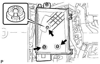 |
Remove the 2 nuts, clip and air cleaner case.
| 23. DISCONNECT NO. 1 RADIATOR HOSE |
| 24. DISCONNECT NO. 2 RADIATOR HOSE |
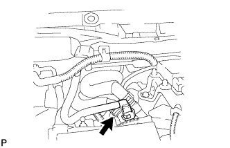
| 25. DISCONNECT NO. 3 FUEL HOSE |
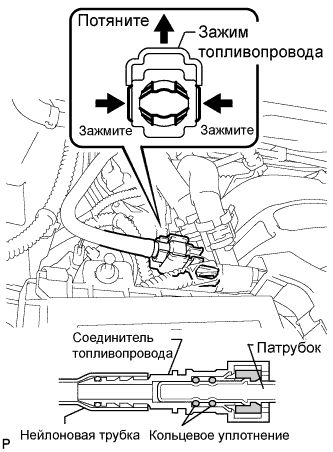 |
Remove the fuel pipe clamp.
Pinch the tube connector and then pull out the fuel hose.
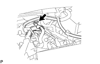
| 26. REMOVE ENGINE ROOM ECU OUTLET DUCT |
 |
Remove the outlet duct.
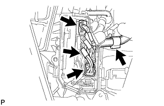
| 27. DISCONNECT HOSES AND CONNECTORS |
 |
Remove the ECM box cover (upper).
Disconnect the 3 ECT connectors and 4 ECM connectors from the ECM box.
 |
Detach the clamp and disconnect the cooler compressor connector.
 |
Detach the clamp and disconnect the 3 connectors with front controller.
 |
Remove the bolt and disconnect the ground wire.
 |
Remove the 2 nuts and disconnect the wires with No. 1 engine room junction block.
 |
Disconnect the 2 heater hoses.
 |
Disconnect the purge line hose.
| 28. REMOVE FRONT EXHAUST PIPE ASSEMBLY |
Remove front exhaust pipe (see page Нажмите здесь).
| 29. REMOVE NO. 1 EXHAUST PIPE SUPPORT BRACKET SUB-ASSEMBLY |
 |
Remove the 2 bolts and bracket.
| 30. REMOVE PROPELLER WITH CENTER BEARING SHAFT ASSEMBLY |
Remove the propeller shaft (see page Нажмите здесь).
| 31. REMOVE FRONT STABILIZER BAR |
Remove the stabilizer bar (see page Нажмите здесь).
| 32. REMOVE FRONT SUSPENSION MEMBER REINFORCEMENT RH |
| 33. REMOVE FRONT SUSPENSION MEMBER REINFORCEMENT LH |
 |
Выверните 4 болта и снимите левое усиление элемента передней подвески с автомобиля.
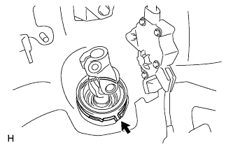
| 34. REMOVE STEERING SLIDING YOKE WITH SHAFT SUB-ASSEMBLY (w/ VGRS) |
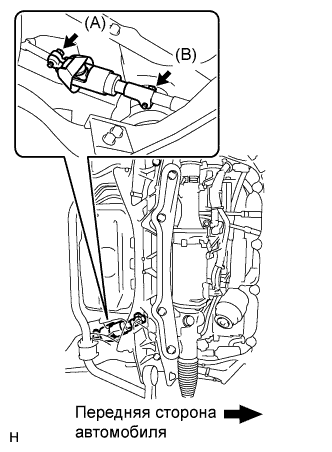 |
Ослабьте болт (A), выверните болт (B), а затем сдвиньте шлицевой хомут рулевого вала вместе с валом.
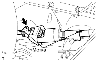 |
Нанесите метки на шлицевой хомут рулевого вала, промежуточный вал № 2 рулевого управления и тягу рулевого управления.
Выверните болт и снимите шлицевой хомут рулевого вала с промежуточного вала № 2 рулевого управления.
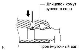 |
Отсоедините вал шлицевого хомута от тяги рулевого управления.
| 35. REMOVE STEERING SLIDING YOKE WITH SHAFT SUB-ASSEMBLY (w/o VGRS) |
|
Ослабьте болт (A), выверните болт (B), а затем сдвиньте шлицевой хомут рулевого вала.
|
Нанесите метки на шлицевой хомут рулевого вала, промежуточный вал № 2 рулевого управления и тягу рулевого управления.
Выверните болт и снимите шлицевой хомут рулевого вала с промежуточного вала № 2 рулевого управления.
|
Отсоедините шлицевой хомут рулевого вала от промежуточного вала рулевого управления.
| 36. REMOVE NO. 2 STEERING INTERMEDIATE SHAFT ASSEMBLY (w/ VGRS) |
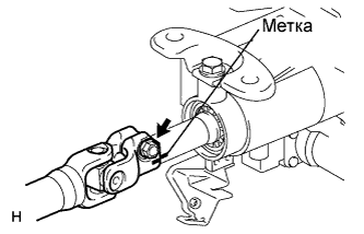 |
Нанесите метки на промежуточный вал № 2 рулевого управления и рулевую колонку.
Выверните болт.
 |
Снимите зажим и промежуточный вал № 2 рулевого управления.
| 37. REMOVE NO. 2 STEERING INTERMEDIATE SHAFT ASSEMBLY (w/o VGRS) |
|
Нанесите метки на промежуточный вал № 2 рулевого управления и рулевую колонку.
Выверните болт.
|
Снимите зажим и промежуточный вал № 2 рулевого управления.
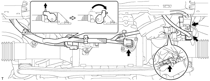
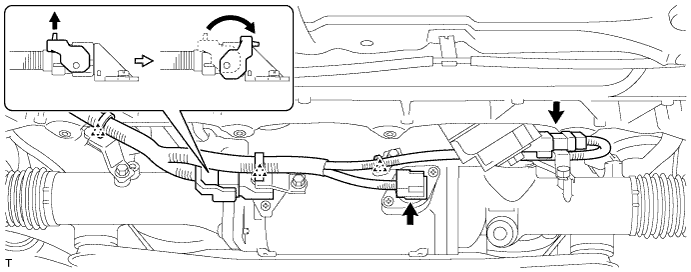
| 38. REMOVE POWER STEERING LINK ASSEMBLY (w/ VGRS) |
Для моделей с левосторонним рулевым управлением:
Расцепите 3 фиксатора и отсоедините 5 разъемов.
Для моделей с правосторонним рулевым управлением:
Расцепите 5 фиксаторов и отсоедините 5 разъемов.
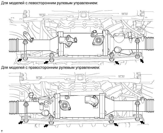
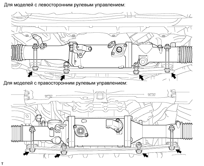
Выверните 4 болта, отверните 4 гайки и снимите тягу рулевого управления с усилителем с передней рамы и кронштейна кожуха рейки.
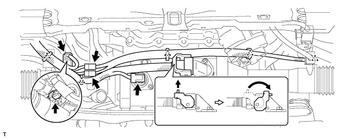
| 39. REMOVE POWER STEERING LINK ASSEMBLY (w/o VGRS) |
Для моделей с левосторонним рулевым управлением:
Расцепите 3 фиксатора и отсоедините 3 разъема.
Для моделей с правосторонним рулевым управлением:
Расцепите 2 фиксатора и отсоедините 3 разъема.
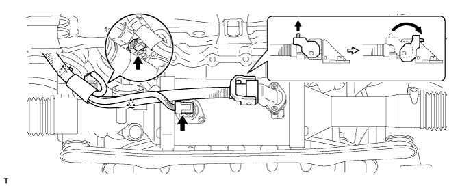
Выверните 4 болта, отверните 4 гайки и снимите тягу рулевого управления с усилителем с передней рамы и кронштейна кожуха рейки.
| 40. REMOVE NO. 2 EXHAUST MANIFOLD HEAT INSULATOR |
 |
Disconnect the sensor connector.
 |
Remove the 3 bolts and heat insulator.
| 41. REMOVE EXHAUST MANIFOLD SUB-ASSEMBLY (for Bank 1) |
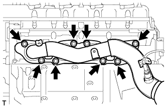 |
Remove the 8 nuts, exhaust manifold and gasket.
| 42. DISCONNECT COOLER COMPRESSOR ASSEMBLY |
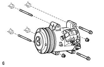 |
Remove the 2 bolts, 2 nuts, 2 stud bolts and disconnect the cooler compressor.
| 43. DISCONNECT FRONT NO. 2 LOWER SUSPENSION ARM SUB-ASSEMBLY |
Disconnect the front No. 2 lower suspension arm (see page Нажмите здесь).
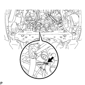
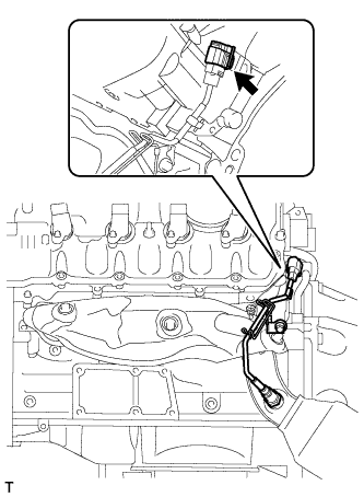
| 44. DISCONNECT FLOOR SHIFT GEAR SHIFTING ROD SUB-ASSEMBLY |
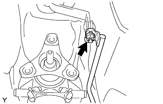 |
Отверните гайку и отсоедините тягу механизма переключения передач.
| 45. REMOVE ENGINE AND TRANSMISSION |
 |
Place a mark (with spray, etc.) over the front right vehicle side attachment area of the crossmember, which is indicated in the illustration.
Place a mark (with spray, etc.) over the front left vehicle side attachment area of the crossmember.
Set an engine lifter underneath the engine.
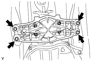 |
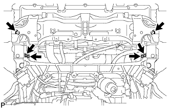
Remove the 4 engine rear mounting member's bolts.
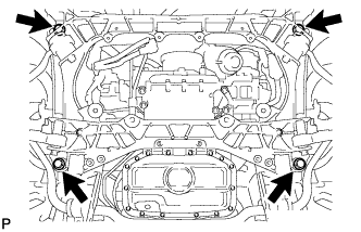 |
Remove the 4 bolts shown in the illustration.
Operate the engine lifter, then slowly remove the engine from the vehicle.
 |
Install the 2 engine hangers with the 2 bolts as shown in the illustration.
| Item | Part No. |
| No. 1 engine hanger | 12281-38030 or 12281-38050 |
| Bolt | 90129-14120 |
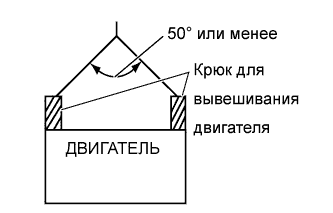 |
Attach an engine sling device and hang the engine with a chain block.
| 46. REMOVE OIL LEVEL DIPSTICK GUIDE |
 |
Remove the dipstick.
Remove the 2 bolts and dipstick guide.
| 47. REMOVE NO. 1 EXHAUST MANIFOLD HEAT INSULATOR |
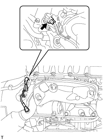 |
Disconnect the sensor connector.
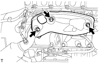 |
Remove the 3 bolts and heat insulator.
| 48. REMOVE EXHAUST MANIFOLD SUB-ASSEMBLY (for Bank 2) |
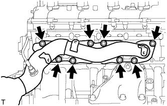 |
Remove the 8 nuts, exhaust manifold and gasket.
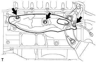
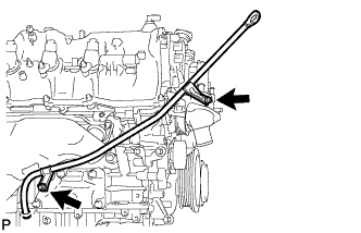
| 49. REMOVE OIL COOLER TUBE |
Выверните 2 болта и снимите 2 зажима.
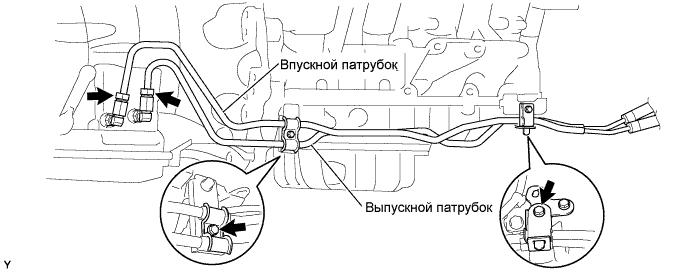
Ослабьте гайки штуцеров впускного и выпускного патрубков масляного радиатора и отсоедините патрубки.
| 50. REMOVE NO. 3 EXHAUST MANIFOLD HEAT INSULATOR |
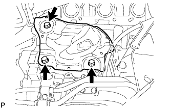 |
Remove the 3 bolts and No. 3 exhaust manifold heat insulator.
| 51. REMOVE STARTER ASSEMBLY |
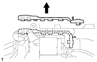 |
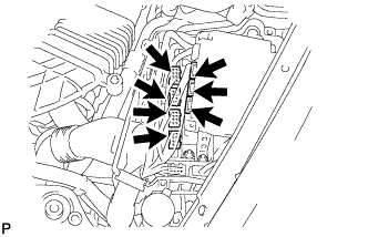
Detach the 11 claws and remove the starter terminal upper cover.
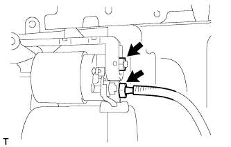 |
Disconnect the starter connector.
Remove the nut and disconnect the wire harness.
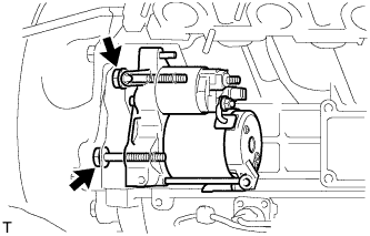 |
Remove the 2 bolts and starter.
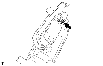 |
Remove the nut and starter terminal lower cover.
 |
Remove the flywheel housing side cover.
| 52. REMOVE AUTOMATIC TRANSMISSION ASSEMBLY |
 |
Снимите боковую крышку картера маховика.
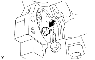 |
Поверните коленчатый вал, чтобы получить доступ к каждому из болтов.
Зафиксируйте гайку шкива коленчатого вала гаечным ключом и выверните 6 болтов.
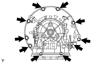 |
Выверните 10 болтов.
Отсоедините и снимите автоматическую трансмиссию.
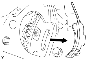
| 53. REMOVE DRIVE PLATE AND RING GEAR SUB-ASSEMBLY |
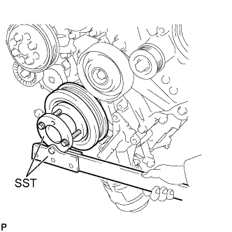 |
Using SST, hold the crankshaft.
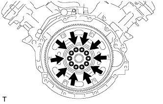 |
Remove the 10 bolts, spacer plate, ring gear and sensor rotor.
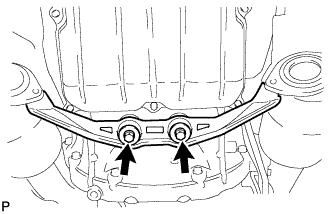
| 54. REMOVE FRONT SUSPENSION CROSSMEMBER SUB-ASSEMBLY |
 |
Remove the 2 nuts, then remove the crossmember from the engine.
| 55. INSTALL ENGINE ON ENGINE STAND |
Install the engine onto an engine stand with the bolts.
Remove the 2 bolts and 2 engine hangers.
| 56. REMOVE ENGINE MOUNTING SPACER |
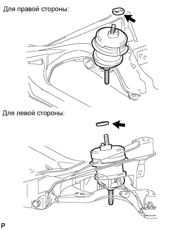 |
Remove the 2 mounting spacers.
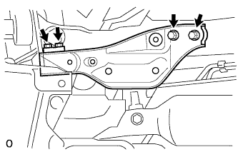
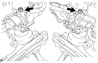
| 57. REMOVE FRONT ENGINE MOUNTING INSULATOR |
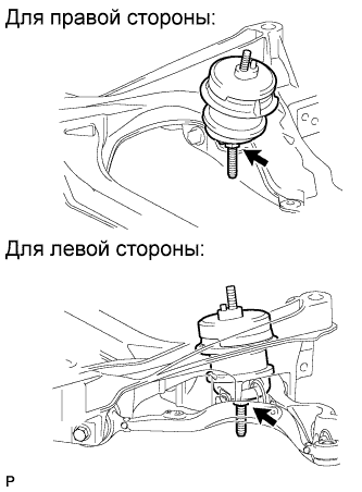 |
Remove the 2 nuts and 2 engine mounting insulators.
