ПЕРЕДНИЙ САЛЬНИК КОЛЕНЧАТОГО ВАЛА > ЗАМЕНА |
| 1. REMOVE V-BANK COVER SUB-ASSEMBLY |
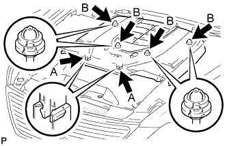 |
While using both hands, lift the rear side of the cover upwards to detach the 4 clips B. Slide the cover towards the front of the vehicle to detach the 2 clips labeled A, and remove the V-bank cover.
| 2. REMOVE AIR CLEANER INLET COVER SUB-ASSEMBLY |
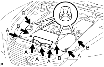 |
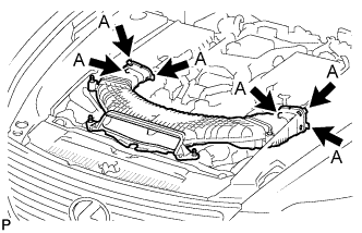
Remove the 5 clips A.
Lift up the air cleaner inlet cover to detach the 4 clips B, and remove the cover.
| 3. REMOVE NO. 1 AIR CLEANER INLET |
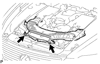 |
Remove the 2 bolts.
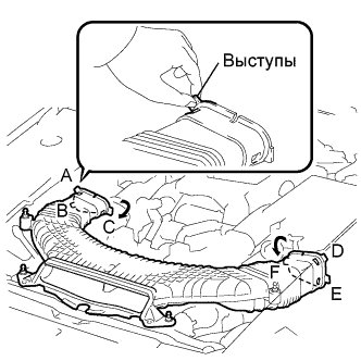 |
Hold the air cleaner inlet by the protrusions A and B, and detach the connections.
Rotate the No. 1 air cleaner inlet as shown in the illustration to detach the protrusion C.
Hold the air cleaner inlet by the protrusions D and E, and detach the connections.
Rotate the No. 1 air cleaner inlet as shown in the illustration to detach the protrusion F.
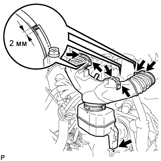
| 4. REMOVE INTAKE AIR CONNECTOR PIPE |
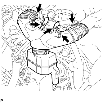 |
Disconnect the No. 1 ventilation hose and No. 2 ventilation hose from the intake air connector pipe.
Loosen the 3 hose clamps, and remove the intake air connector pipe.
| 5. REMOVE V-RIBBED BELT |
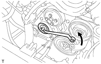 |
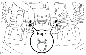
Rotate the tensioner pulley counterclockwise to loosen the belt tension.
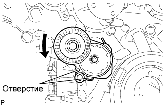 |
While turning the belt tensioner counterclockwise, align the holes. Insert a bar of φ5 mm (0.20 in.) into the holes to fix the belt tensioner in place.
Remove the V belt.
| 6. REMOVE RESONATOR BRACKET SUB-ASSEMBLY |
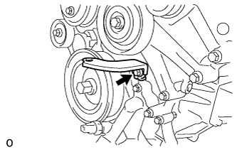 |
Remove the bolt and resonator bracket.
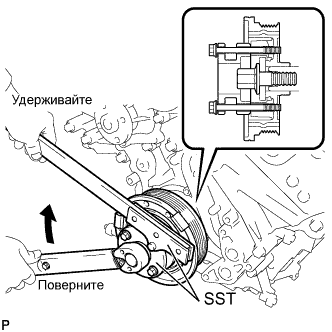
| 7. REMOVE CRANKSHAFT PULLEY |
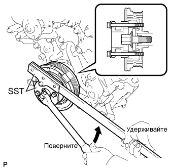 |
Using SST, loosen the crankshaft pulley set bolt.
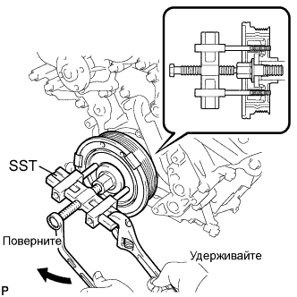 |
Using the pulley set bolt and SST, remove the crankshaft pulley.
| 8. REMOVE CRANKSHAFT TIMING GEAR KEY |
 |
Remove the crankshaft timing gear key from the crankshaft.
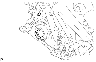
| 9. REMOVE TIMING CHAIN CASE OIL SEAL |
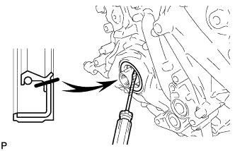 |
Remove the oil seal with a screwdriver.
| 10. INSTALL TIMING CHAIN CASE OIL SEAL |
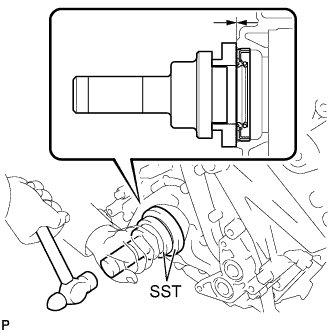 |
Using SST, tap in a new oil seal until its surface is flush with the timing chain case edge.
| 11. INSTALL CRANKSHAFT TIMING GEAR KEY |
|
Install the crankshaft timing gear key.
| 12. INSTALL CRANKSHAFT PULLEY |
Align the pulley set key with the key groove of the pulley, and slide on the pulley.
 |
Using SST, install the pulley bolt.
| 13. INSTALL RESONATOR BRACKET SUB-ASSEMBLY |
|
Install the resonator bracket with the bolt.
| 14. INSTALL V-RIBBED BELT |
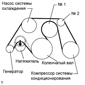 |
Install the V belt as shown in the illustration.
Rotate the tensioner pulley counterclockwise, and then remove the fix bar.
| 15. INSTALL INTAKE AIR CONNECTOR PIPE |
 |
Align the protrusion of the intake air resonator with the cutout of the bracket and insert the protrusion.
Install the intake air connector pipe with the 3 hose clamps.
 |
Connect the No. 1 ventilation hose and No. 2 ventilation hose to the intake air connector pipe.
| 16. INSTALL NO. 1 AIR CLEANER INLET |
 |
Align the holes with the connection areas labeled A, and attach the No. 1 air cleaner inlet.
|
Install the No. 1 air cleaner inlet with the 2 bolts.
| 17. INSTALL AIR CLEANER INLET COVER SUB-ASSEMBLY |
|
Attach the 4 clips B.
Install the air cleaner inlet cover with the 5 clips A.
| 18. INSTALL V-BANK COVER SUB-ASSEMBLY |
|
After sliding the cover from the vehicle front to the rear to attaching the 2 clips A, attach the 4 clips B and install the V bank cover.
