БЛОК ЦИЛИНДРОВ > ПРОВЕРКА |
| 1. INSPECT NO. 1 OIL NOZZLE SUB-ASSEMBLY |
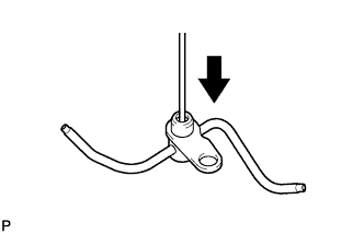 |
Push the check valve while covering A, and apply air into B. Check that air passes through the oil nozzle. If air cannot pass through, clean or replace the oil nozzle.
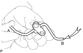 |
While covering A, apply air into B. Then check the oil nozzle for damage or clogging. If there is an air leak, clean or replace the oil nozzle.
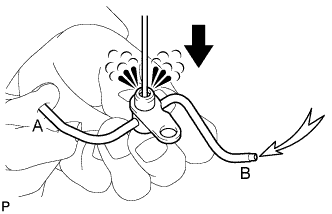 |
Push the check valve while covering A, and apply air into B. Check that air passes through the oil nozzle. If air cannot pass through, clean or replace the oil nozzle.
| 2. INSPECT CYLINDER BLOCK FOR WARPAGE |
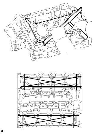 |
Using a precision straightedge and feeler gauge, measure the warpage of the contact surface of the cylinder head gasket.
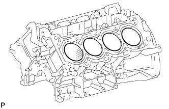 |
Visually check the cylinder for vertical scratches.
If deep scratches are present, rebore all 8 cylinders.
If necessary, replace the cylinder block.
| 3. INSPECT CYLINDER BORE |
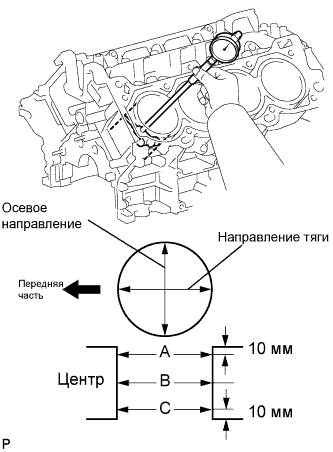 |
Using a cylinder gauge, measure the cylinder bore diameter at positions A, B and C in the thrust and axial directions.
| 4. INSPECT PISTON SUB-ASSEMBLY WITH PIN |
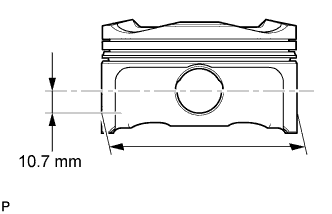 |
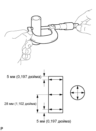
Using a micrometer, measure the piston diameter at a position that is 10.7 mm (0.421 in.) downward from the center of the piston pin hole (refer to the illustration).
| 5. INSPECT PISTON OIL CLEARANCE |
Measure the cylinder bore diameter in the thrust direction.
Subtract the piston diameter measurement from the cylinder bore diameter measurement.
| 6. INSPECT RING GROOVE CLEARANCE |
 |
Using a feeler gauge, measure the clearance between a new piston ring and the wall of the ring groove.
| Item | Specified Condition |
| No. 1 | 0.020 to 0.070 mm (0.0008 to 0.0028 in.) |
| No. 2 | 0.020 to 0.060 mm (0.0008 to 0.0024 in.) |
| Oil | 0.020 to 0.070 mm (0.0008 to 0.0028 in.) |
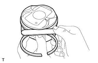
| 7. INSPECT PISTON RING END GAP |
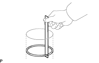
Insert the piston ring into the cylinder bore.
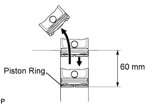 |
Using a piston, push the piston ring a little beyond the bottom of the ring travel, 60 mm (2.362 in.) from the top of the cylinder block.
 |
Using a feeler gauge, measure the end gap.
| Item | Specified Condition |
| No. 1 | 0.23 to 0.33 mm (0.0091 to 0.0130 in.) |
| No. 2 | 0.35 to 0.45 mm (0.0138 to 0.0177 in.) |
| Oil | 0.10 to 0.40 mm (0.0039 to 0.0157 in.) |
| Item | Specified Condition |
| No. 1 | 0.40 mm (0.0157 in.) |
| No. 2 | 0.50 mm (0.0197 in.) |
| Oil | 0.45 mm (0.0177 in.) |
| 8. INSPECT PISTON PIN OIL CLEARANCE |
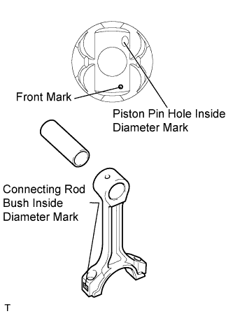 |
Check each mark on the piston, piston pin and connecting rod.
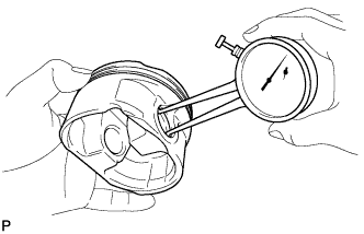 |
Using a caliper gauge, measure the inside diameter of the piston pin hole.
| Mark | Specified Condition |
| A | 21.998 to 22.001 mm (0.8661 to 0.8662 in.) |
| B | 22.002 to 22.004 mm (0.8662 to 0.8663 in.) |
| C | 22.005 to 22.007 mm (0.8663 to 0.8664 in.) |
 |
Using a micrometer, measure the piston pin diameter.
| Mark | Specified Condition |
| A | 21.997 to 22.000 mm (0.8660 to 0.8661 in.) |
| B | 22.001 to 22.003 mm (0.8662 to 0.8663 in.) |
| C | 22.004 to 22.006 mm (0.8663 to 0.8664 in.) |
Subtract the piston pin diameter measurement from the piston pin hole diameter measurement.
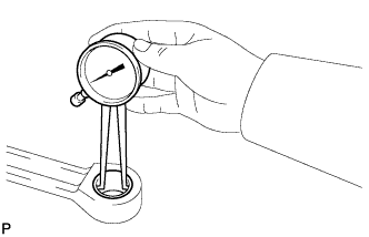 |
Using a caliper gauge, measure the inside diameter of the connecting rod bush.
| Mark | Specified Condition |
| A | 22.005 to 22.008 mm (0.8663 to 0.8665 in.) |
| B | 22.009 to 22.011 mm (0.8665 to 0.8666 in.) |
| C | 22.012 to 22.014 mm (0.8666 to 0.8667 in.) |
Subtract the piston pin diameter measurement from the bush inside diameter measurement.
| 9. INSPECT CONNECTING ROD SUB-ASSEMBLY |
Using a rod aligner and feeler gauge, check the connecting rod alignment.
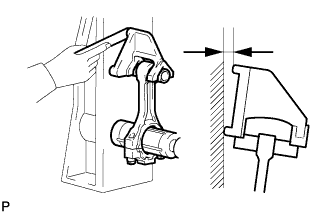 |
Check for bend.
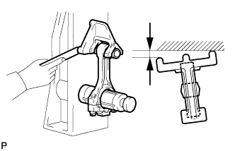 |
Check for twist.
| 10. INSPECT CONNECTING ROD BOLT |
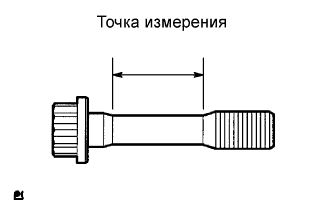 |
Using a vernier caliper, measure the tension portion diameter of the bolt.
| 11. INSPECT CRANKSHAFT |
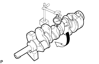 |
Inspect for circle runout.
Place the crankshaft on V-blocks.
Using a dial indicator, measure the circle runout at the center journal.
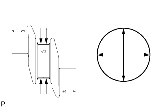 |
Inspect the main journals.
Using a micrometer, measure the diameter of each main journal.
Check each main journal for taper and out-of-round as shown in the illustration.
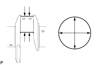 |
Inspect the crank pin.
Using a micrometer, measure the diameter of each crank pin.
Check each crank pin for taper and out-of-round as shown in the illustration.
| 12. INSPECT CRANKSHAFT OIL CLEARANCE |
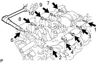 |
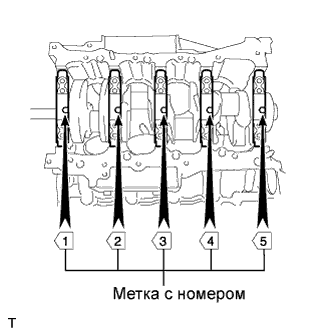
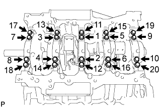
Uniformly loosen and remove the 10 bearing cap bolts and 10 seal washers in several steps, in the sequence shown the illustration.
 |
Uniformly loosen the 20 bearing cap bolts in several steps, in the sequence shown in the illustration.
 |
Using a screwdriver, pry out the main bearing caps. Remove the 5 main bearing caps and lower bearings.
Clean each main journal and bearing.
Check each main journal and bearing for pitting and scratches.
Place the crankshaft on the cylinder block.
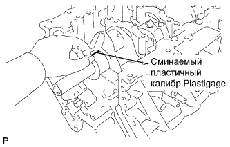 |
Lay a strip of Plastigage across each journal.
 |
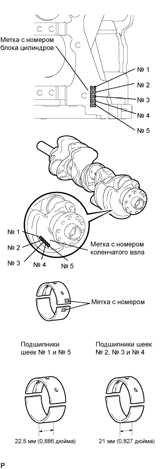
Examine the front marks and numbers, and install the bearing caps on the cylinder block.
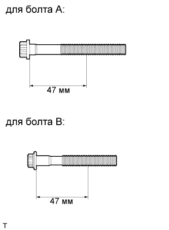
Apply a light coat of engine oil on the threads and under the heads of the bearing cap bolts.
Place the crankshaft bearing cap on the cylinder block.
Temporarily install the 10 main bearing cap bolts to the inside positions.
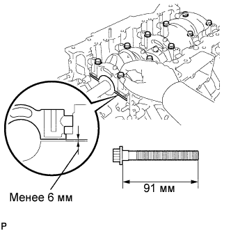 |
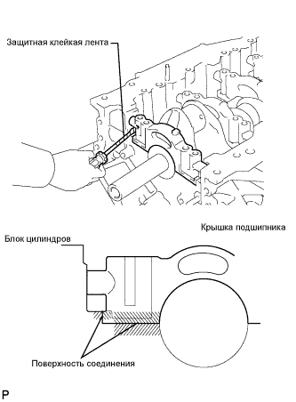
Insert the main bearing cap by hand until the clearance between the main bearing cap and cylinder block is less than 6 mm (0.23 in.) by marking the 2 internal bearing cap bolts as a guide.
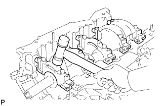 |
Using a plastic-faced hammer, lightly tap the bearing cap to ensure a proper fit.
Apply a light coat of engine oil to the threads and under the heads of the 10 main bearing cap bolts.
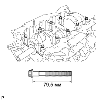 |
Temporarily install the 10 main bearing cap bolts to the outside positions.
 |
Step 1:
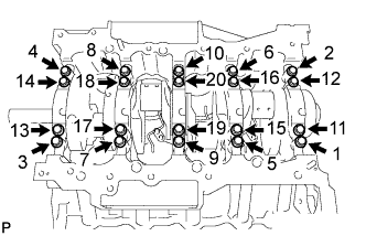
Install and uniformly tighten the 20 main bearing cap bolts in the sequence shown in the illustration.
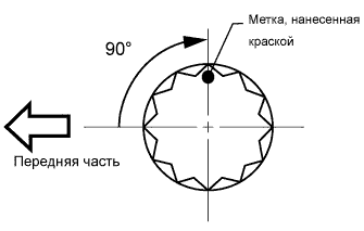 |
Step 2:
Mark the front of the bearing cap bolts with paint.
Tighten the bearing cap bolts another 90° in the order shown in step 1.
Check that the painted marks are now at a 90° angle to the front.
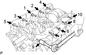 |
Install and uniformly tighten the 10 main bearing cap bolts and 10 seal washers in several steps, in the sequence shown in the illustration.
Remove the 30 bolts and bearing caps.
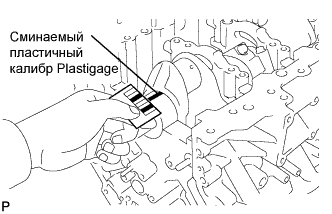  |
Measure the plastigage at its widest point.
| Number Mark | Specified Condition |
| No. 1 and No. 5 journal | 0.017 to 0.030 mm (0.0007 to 0.0012 in.) |
| Other journal | 0.024 to 0.037 mm (0.0009 to 0.0015 in.) |
| Number Mark | Specified Condition |
| No. 1 and No. 5 journal | 0.050 mm (0.0020 in.) |
| Other journal | 0.060 mm (0.0024 in.) |
| Number Mark | Specified Condition |
| 00 | 66.999 to 67.000 mm (2.63776 to 2.63780 in.) |
| 01 | 66.998 to 66.999 mm (2.63772 to 2.63776 in.) |
| 02 | 66.997 to 66.998 mm (2.63768 to 2.63772 in.) |
| 03 | 66.996 to 66.997 mm (2.63764 to 2.63768 in.) |
| 04 | 66.995 to 66.996 mm (2.63760 to 2.63764 in.) |
| 05 | 66.994 to 66.995 mm (2.63756 to 2.63760 in.) |
| 06 | 66.993 to 66.994 mm (2.63752 to 2.63756 in.) |
| 07 | 66.992 to 66.993 mm (2.63748 to 2.63752 in.) |
| 08 | 66.991 to 66.992 mm (2.63744 to 2.63748 in.) |
| 09 | 66.990 to 66.991 mm (2.63740 to 2.63744 in.) |
| 10 | 66.989 to 66.990 mm (2.63736 to 2.63740 in.) |
| 11 | 66.988 to 66.989 mm (2.63736 to 2.63736 in.) |
| (A) + (B) | Upper bearing | Lower bearing | ||
| Number Mark | Specified condition | Number Mark | Specified condition | |
| 00 to 02 | 4 | 2.501 to 2.504 (0.0985 to 0.0986 in.) | 5 | 2.488 to 2.491 (0.0980 to 0.0981 in.) |
| 03 to 05 | 5 | 2.504 to 2.507 (0.0986 to 0.0987 in.) | 5 | 2.488 to 2.491 (0.0988 to 0.0981 in.) |
| 06 to 08 | 5 | 2.504 to 2.507 (0.0986 to 0.0987 in.) | 6 | 2.491 to 2.494 (0.0981 to 0.0982 in.) |
| 09 to 11 | 6 | 2.507 to 2.510 (0.0987 to 0.0988 in.) | 6 | 2.491 to 2.494 (0.0981 to 0.0982 in.) |
| 12 to 14 | 6 | 2.507 to 2.510 (0.0987 to 0.0988 in.) | 7 | 2.494 to 2.497 (0.0982 to 0.0983 in.) |
| 15 to 17 | 7 | 2.510 to 2.513 (0.0988 to 0.0989 in.) | 7 | 2.494 to 2.497 (0.0982 to 0.0983 in.) |
| 18 to 20 | 7 | 2.510 to 2.513 (0.0988 to 0.0989 in.) | 8 | 2.497 to 2.500 (0.0983 to 0.0984 in.) |
| 21 to 23 | 8 | 2.513 to 2.516 (0.0989 to 0.0991 in.) | 8 | 2.497 to 2.500 (0.0983 to 0.0984 in.) |
| 24 to 26 | 8 | 2.513 to 2.516 (0.0989 to 0.0991 in.) | 9 | 2.500 to 2.503 (0.0984 to 0.0985 in.) |
| 27 to 28 | 9 | 2.516 to 2.519 (0.0991 to 0.0992 in.) | 9 | 2.500 to 2.503 (0.0984 to 0.0985 in.) |
| (A) + (B) | Upper bearing | Lower bearing | ||
| Number Mark | Specified condition | Number Mark | Specified condition | |
| 00 to 02 | 3 | 2.482 to 2.485 (0.0977 to 0.0978 in.) | 4 | 2.501 to 2.504 (0.0985 to 0.0986 in.) |
| 03 to 05 | 4 | 2.485 to 2.488 (0.0978 to 0.0980 in.) | 4 | 2.501 to 2.504 (0.0985 to 0.0986 in.) |
| 06 to 08 | 4 | 2.485 to 2.488 (0.0978 to 0.0980 in.) | 5 | 2.504 to 2.507 (0.0986 to 0.0987 in.) |
| 09 to 11 | 5 | 2.488 to 2.491 (0.0980 to 0.0981 in.) | 5 | 2.504 to 2.507 (0.0986 to 0.0987 in.) |
| 12 to 14 | 5 | 2.488 to 2.491 (0.0980 to 0.0981 in.) | 6 | 2.507 to 2.510 (0.0987 to 0.0988 in.) |
| 15 to 17 | 6 | 2.491 to 2.494 (0.0981 to 0.0982 in.) | 6 | 2.507 to 2.510 (0.0987 to 0.0988 in.) |
| 18 to 20 | 6 | 2.491 to 2.494 (0.0981 to 0.0982 in.) | 7 | 2.510 to 2.513 (0.0988 to 0.0989 in.) |
| 21 to 23 | 7 | 2.494 to 2.497 (0.0982 to 0.0983 in.) | 7 | 2.510 to 2.513 (0.0988 to 0.0989 in.) |
| 24 to 26 | 7 | 2.494 to 2.497 (0.0982 to 0.0983 in.) | 8 | 2.513 to 2.516 (0.0989 to 0.0991 in.) |
| 27 to 28 | 8 | 2.497 to 2.500 (0.0983 to 0.0984 in.) | 8 | 2.513 to 2.516 (0.0989 to 0.0991 in.) |
Completely remove the Plastigage.
| 13. INSPECT CRANKSHAFT BEARING CAP SET BOLT |
 |
Using a vernier caliper, measure the minimum diameter of the elongated thread at the measuring point.
