БЛОК ЦИЛИНДРОВ > РАЗБОРКА |
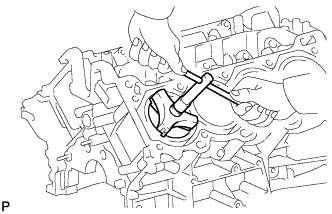
| 1. INSPECT CONNECTING ROD THRUST CLEARANCE |
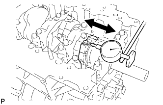 |
Using a dial indicator, measure the thrust clearance while moving the connecting rod back and forth.
| 2. INSPECT CONNECTING ROD OIL CLEARANCE |
Check that the front mark on the connecting rod and cap are aligned to ensure the correct reassembly.
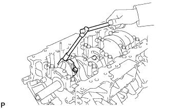 |
Remove the 2 connecting rod cap bolts.
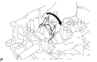 |
Using the 2 removed connecting rod cap bolts, remove the connecting rod cap and lower bearing by wiggling the connecting rod cap right and left.
Clean the crank pin and bearing.
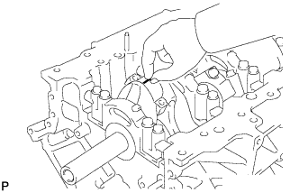 |
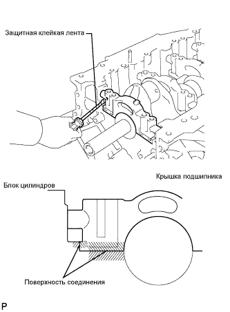
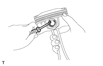
Lay a strip of Plastigage on the crank pin.
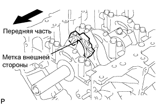 |
Check that the front mark of the connecting rod cap is facing forward.
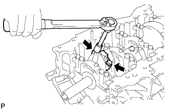 |
Install and alternately tighten the bolts of the connecting rod cap in several steps.
Mark the front side of each connecting cap bolt with paint.
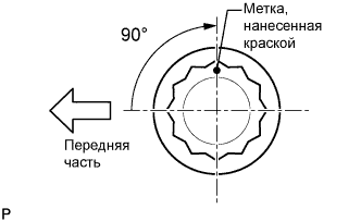 |
Retighten the cap bolts by 90° as shown.
Check that the painted marks are now at a 90° angle to the front.
Remove the 2 connecting rod cap bolts.
Using the 2 removed connecting rod cap bolts, remove the connecting rod cap and lower bearing by wiggling the connecting rod cap right and left.
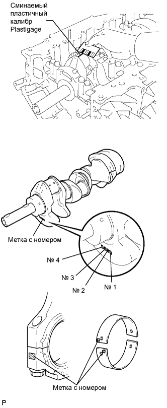 |
Measure the Plastigage at its widest point.
| Mark | Thickness |
| 2 | 1.489 to 1.492 mm (0.0586 to0.0587 in.) |
| 3 | 1.492 to 1.495 mm (0.0587 to 0.0589 in.) |
| 4 | 1.495 to 1.498 mm (0.0589 to 0.0590 in.) |
| 5 | 1.498 to 1.501 mm (0.0590 to 0.0591 in.) |
| 6 | 1.501 to 1.504 mm (0.0591 to 0.0592 in.) |
| 7 | 1.504 to 1.507 mm (0.0592 to 0.0593 in.) |
| Mark | Thickness |
| 1 | 56.000 to 56.006 mm (2.2047 to 2.2050 in.) |
| 2 | 56.007 to 56.012 mm (2.2050 to 2.2052 in.) |
| 3 | 56.013 to 56.018 mm (2.2052 to 2.2054 in.) |
| 4 | 56.019 to 56.024 mm (2.2055 to 2.2057 in.) |
| Mark | Thickness |
| 1 | 52.995 to 53.000 mm (2.0864 to 2.0866 in.) |
| 2 | 52.989 to 52.994 mm (2.0862 to 2.0864 in.) |
| 3 | 52.982 to 52.998 mm (2.0859 to 2.0865 in.) |
Completely remove the Plastigage.
Perform the inspection above for each cylinder.
| 3. REMOVE PISTON AND CONNECTING ROD |
 |
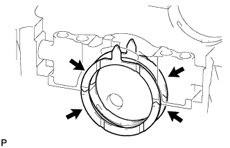
Using a ridge reamer, remove all the carbon from the top of the cylinder.
Remove the 16 cap bolts and 8 connecting rod caps.
Push the 8 pistons, 8 connecting rods and 8 upper bearings through the top of the cylinder block.
| 4. REMOVE CONNECTING ROD BEARING |
Remove the connecting rod bearings from the connecting rods and connecting rod caps.
| 5. INSPECT CRANKSHAFT THRUST CLEARANCE |
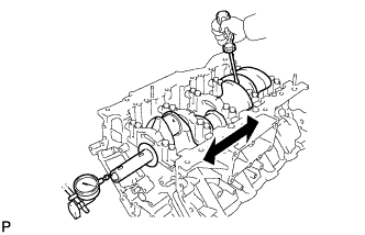 |
Using a dial indicator, measure the thrust clearance while prying the crankshaft back and forth with a screwdriver.
| 6. REMOVE CRANKSHAFT |
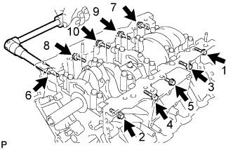 |
Uniformly loosen and remove the 10 bearing cap bolts and 10 seal washers in several steps, in the sequence shown the illustration.
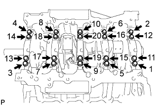 |
Uniformly loosen the 20 bearing cap bolts in several steps, in the sequence shown in the illustration.
 |
Using a screwdriver, pry out the main bearing caps. Remove the 5 main bearing caps and lower bearings.
Remove the crankshaft.
| 7. REMOVE CRANKSHAFT BEARING |
Remove the crankshaft bearings from the bearing caps and cylinder block.
| 8. REMOVE CRANKSHAFT THRUST WASHER SET |
 |
Remove the thrust washer set from the cylinder block and No. 3 bearing cap.
| 9. REMOVE NO. 1 OIL NOZZLE SUB-ASSEMBLY |
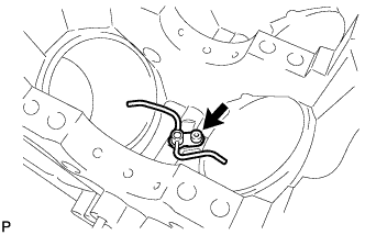 |
Using a 5 mm hexagon wrench, remove the 4 bolts and 4 oil nozzles.
| 10. REMOVE PISTON RING SET |
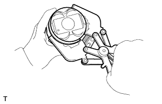 |
Using a piston ring expander, remove the 2 compression rings.
Using a piston ring expander, remove the oil ring.
Remove the oil ring expander by hand.
| 11. REMOVE PISTON WITH PIN SUB-ASSEMBLY |
Disconnect the connecting rod from the piston.
 |
Using a screwdriver, pry off the snap rings from the piston.
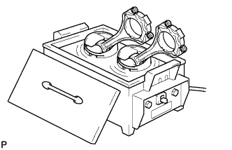 |
Gradually heat the piston to approximately 89°C (176°F).
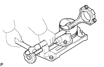 |
Using a brass bar and plastic-faced hammer, lightly tap out the piston pin and remove the connecting rod.
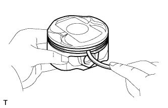
Clean piston
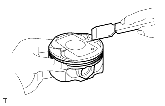 |
Using a gasket scraper, remove the carbon from the piston top.
 |
Using a groove cleaning tool or broken ring, clean the piston ring grooves.
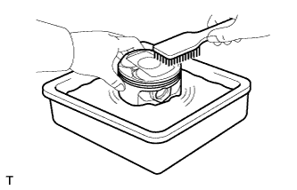 |
Using solvent and a brush, thoroughly clean the piston.
