- Open in Heated Oxygen (HO2) sensor heater circuit
- Heated Oxygen (HO2) sensor heater
- EFI Relay
- ECM
| Last Modified: 4-30-2014 | 6.6 C | Doc ID: RM000000PFA00IX |
| Model Year: 2006 | Model: LX470 | Prod Date Range: [05/2005 - ] |
| Title: 2UZ-FE ENGINE CONTROL SYSTEM: SFI SYSTEM: P0037,P0038,P0057,P0058; Oxygen Sensor Heater Control Circuit Low (Bank 1 Sensor 2); 2006 MY LX470 [05/2005 - ] | ||
|
DTC |
P0037 |
Oxygen Sensor Heater Control Circuit Low (Bank 1 Sensor 2) |
|
DTC |
P0038 |
Oxygen Sensor Heater Control Circuit High (Bank 1 Sensor 2) |
|
DTC |
P0057 |
Oxygen Sensor Heater Control Circuit Low (Bank 2 Sensor 2) |
|
DTC |
P0058 |
Oxygen Sensor Heater Control Circuit High (Bank 2 Sensor 2) |
DESCRIPTION
-
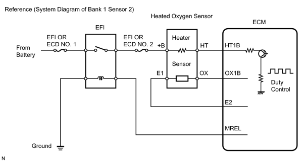
Refer to DTC P0136
![2006 MY LX470 [05/2005 - ]; 2UZ-FE ENGINE CONTROL SYSTEM: SFI SYSTEM: P0136-P0138,P0156-P0158; Oxygen Sensor Circuit Malfunction (Bank 1 Sensor 2)+](../../../../stylegraphics/info.gif "2006 MY LX470 [05/2005 - ]; 2UZ-FE ENGINE CONTROL SYSTEM: SFI SYSTEM: P0136-P0138,P0156-P0158; Oxygen Sensor Circuit Malfunction (Bank 1 Sensor 2)+") .
.
HINT:
- Sensor 2 refers to the sensor mounted behind the Three-Way Catalytic Converter (TWC) and located far from the engine assembly.
- When any of these DTCs are set, the ECM enters fail-safe mode. The ECM turns off the Heated Oxygen (HO2) Sensor heater in fail-safe mode. Fail-safe mode continues until the ignition switch is turned OFF.
-
The ECM provides a pulse width modulated control circuit to adjust the current through the heater. The HO2 sensor heater circuit uses a relay on the +B side of the circuit.
|
DTC No. |
DTC Detection Condition |
Trouble Area |
|---|---|---|
|
P0037 P0057 |
Heated Oxygen (HO2) sensor heater current less than 0.3 A (1 trip detection logic) |
|
|
P0038 P0058 |
Heated Oxygen (HO2) sensor heater current more than 2.0 A (1 trip detection logic) |
|
HINT:
- Bank 1 refers to the bank that includes No. 1 cylinder.
- Bank 2 refers to the bank that does not include No. 1 cylinder.
- Sensor 1 refers to the sensor closest to the engine assembly.
- Sensor 2 refers to the sensor farthest away from the engine assembly.
MONITOR DESCRIPTION
- The sensing position of the Heated Oxygen (HO2) sensor has a zirconia element which is used to detect the oxygen concentration in the exhaust gas. If the zirconia element is at the appropriate temperature, and the difference between the oxygen concentrations surrounding the inside and outside surfaces of the sensor is large, the zirconia element generates voltage signals. In order to increase the oxygen concentration detecting capacity of the zirconia element, the ECM supplements the heat from the exhaust with heat from a heating element inside the sensor. When the current in the sensor heater is outside the standard operating range, the ECM interprets this as a malfunction in the sensor heater and sets a DTC.
- Example:
- The ECM sets DTC P0038 or P0058 when the current in the HO2 sensor heater is more than 2 A. Conversely, when the heater current is less than 0.3 A, DTC P0037 or P0057 is set.
MONITOR STRATEGY
|
Related DTCs |
P0037: Heated oxygen sensor heater (bank 1) range check (low current) P0038: Heated oxygen sensor heater (bank 1) range check (high current) P0057: Heated oxygen sensor heater (bank 2) range check (low current) P0058: Heated oxygen sensor heater (bank 2) range check (high current) |
|
Required sensors / components |
Heated oxygen sensor heater (bank 1 and 2) |
|
Required sensors / components |
Vehicle speed sensor |
|
Frequency of operation |
Continuous |
|
Duration |
P0037 and P0057: 0.5 seconds P0038 and P0058: 0.3 seconds |
|
MIL operation |
Immediate |
|
Sequence of operation |
None |
TYPICAL ENABLING CONDITIONS
All:
|
Battery voltage |
10.5 V or more |
|
Engine |
Running |
|
Starter |
OFF |
|
Catalyst intrusive monitoring |
Not operating |
|
Intrusive heating |
Not operating |
P0037 and P0057 (Low current):
|
When the following conditions are met |
0.5 sec. or more |
|
(a) Following conditions are met |
- |
|
Learned heater current during heater OFF |
Completed |
|
Intrusive heating |
Not operating |
|
Heating is OFF |
Less than 0.1 seconds |
|
Heater current |
Less than 0.3 A |
|
Intrusive heating for high current monitor |
Not operating |
|
(b) Following condition is met |
- |
|
Time after heaters are OFF |
1 second or or more |
P0038 and P0058 (High current):
|
When the following conditions are met |
0.3 sec. or more |
|
(a) Following conditions are met |
- |
|
Learned heater current during heater OFF |
Completed |
|
Intrusive heating |
Not operating |
|
Heating is OFF |
Less than 0.1 second |
|
Heater current |
2 A or more |
|
(b) Following condition is met |
- |
|
Time after heaters are OFF |
1 second or or more |
TYPICAL MALFUNCTION THRESHOLDS
P0037 and P0057 (Low current):
|
Following conditions are met |
- |
|
Heater |
ON |
|
Heater current |
Less than 0.3 A |
|
Intrusive heating |
Operating |
P0038 and P0058 (High current):
|
Either A or B is met |
- |
|
A. Following conditions are met |
With intrusive heating |
|
Heater |
ON |
|
Heater current |
2 A or more |
|
B. Following conditions are met |
Without intrusive heating |
|
Intrusive heating of learned heater current |
Operating |
|
Learned heater current during heater OFF |
Operating |
|
Heater current |
More than 2 A |
COMPONENT OPERATING RANGE
|
Heated Oxygen (HO2) sensor heater current |
0.4 to 1 A (when engine idles, HO2 sensor warmed up and battery voltage 11 to 14 V) |
MONITOR RESULT
-
Detailed information on Checking Monitor Status
.
The test value and test limit information are in the following table. Check the monitor result and test values after performing the monitor drive pattern (refer to "Confirmation Monitor").
- Monitor Identification Date (MID) is assigned to each emission-related component.
- Test Identification Date (TID) is assigned to each emission-related component.
- Scaling is used to calculate the test value indicated on generic OBD II scan tools.
Heated oxygen sensor heater (Bank 1 sensor 2):
|
MID |
TID |
Scaling |
Description of Test Value |
Minimum Test Limit |
Maximum Test Limit |
|
$42 |
$90 |
Multiply by 0.001 (A) |
Maximum sensor heater current |
Minimum test limit |
Maximum test limit |
Heated oxygen sensor heater (Bank 2 sensor 2):
|
MID |
TID |
Scaling |
Description of Test Value |
Minimum Test Limit |
Maximum Test Limit |
|
$46 |
$90 |
Multiply by 0.001 (A) |
Maximum sensor heater current |
Minimum test limit |
Maximum test limit |
WIRING DIAGRAM
Refer to DTC P0136
.
INSPECTION PROCEDURE
HINT:
- If other DTCs relating to different systems that have terminal E2 as the ground terminal are output simultaneously, terminal E2 may have an open circuit.
- Read freeze frame data using the intelligent tester. Freeze frame data records the engine conditions when malfunctions are detected. When troubleshooting, freeze frame data can help determine if the vehicle was moving or stationary, if the engine was warmed up or not, if the air fuel ratio was lean or rich, and other data from the time the malfunction occurred.
PROCEDURE
|
1. |
INSPECT HEATED OXYGEN SENSOR (HEATER RESISTANCE) |
|
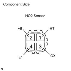
(a) Disconnect the H8 or H17 Heated Oxygen (HO2) sensor connectors. (b) Measure the resistance of the HO2 sensor connector. Standard resistance (Bank 1, 2 sensor 2):
(c) Reconnect the HO2 sensor connector. |
|
| NG |

|
|

|
2. |
INSPECT EFI RELAY (Marking: EFI OR ECD) |
|
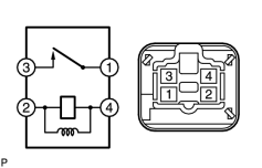
(a) Remove the EFI relay from the engine room relay block. (b) Measure the resistance of the EFI relay. Standard resistance:
(c) Reinstall the EFI relay. |
|
| NG |
|
|
|
3. |
INSPECT ECM (HT1B OR HT2B VOLTAGE) |
|
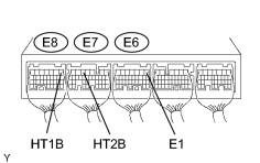
(a) Turn the ignition switch ON. (b) Measure the voltage of the E6, E7 and E8 ECM connectors. Standard resistance:
HINT:
|
|
| OK |
|
|
|
4. |
CHECK HARNESS AND CONNECTOR (HEATED OXYGEN SENSOR - EFI RELAY) |
(a)
Check harness and connector
.
| NG |
|
|
|
5. |
CHECK HARNESS AND CONNECTOR (HEATED OXYGEN SENSOR - ECM) |
(a)
Check harness and connector
.
| NG |
|
| OK |
|

|

|