| Last Modified: 4-30-2014 | 6.6 A | Doc ID: RM000000SLE007X |
| Model Year: 2006 | Model: LX470 | Prod Date Range: [05/2005 - ] |
| Title: 2UZ-FE ENGINE MECHANICAL: TIMING BELT: REMOVAL; 2006 MY LX470 [05/2005 - ] | ||
REMOVAL
1. DISCONNECT CABLE FROM NEGATIVE BATTERY TERMINAL
CAUTION:
Wait at least 90 seconds after disconnecting the cable from the negative (-) battery terminal to prevent airbag activation.
2. REMOVE ENGINE REAR UNDER COVER
(a) Remove the 8 bolts and engine under cover.
3. REMOVE NO. 1 ENGINE UNDER COVER
(a) Remove the 5 bolts and engine under cover.
4.
DRAIN ENGINE COOLANT
![2006 MY LX470 [05/2005 - ]; 2UZ-FE COOLING: COOLANT: REPLACEMENT+](../../../../stylegraphics/info.gif "2006 MY LX470 [05/2005 - ]; 2UZ-FE COOLING: COOLANT: REPLACEMENT+")
5.
REMOVE V-BANK COVER
6.
REMOVE AIR CLEANER HOSE ASSEMBLY
7. REMOVE AIR CLEANER ASSEMBLY
(a) Disconnect the MAF meter connector.
(b) Remove the air cleaner cap and air cleaner element.
(c) Remove the 3 bolts and air cleaner case assembly.
8.
DISCONNECT NO. 1 RADIATOR HOSE
9.
DISCONNECT NO. 2 RADIATOR HOSE
10.
DISCONNECT NO. 1 OIL COOLER INLET TUBE
11.
DISCONNECT NO. 1 OIL COOLER OUTLET TUBE
12.
REMOVE DRIVE BELT
13.
REMOVE RADIATOR ASSEMBLY
14.
DISCONNECT VANE PUMP ASSEMBLY
15.
REMOVE GENERATOR ASSEMBLY
16.
DISCONNECT COMPRESSOR ASSEMBLY
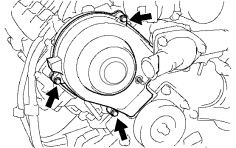
17. REMOVE NO. 3 TIMING BELT COVER SUB-ASSEMBLY RH
|
(a) Remove the cap nut, 3 bolts, timing belt cover and gasket. |
|
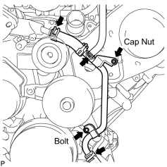
18. REMOVE OIL COOLER PIPE
|
(a) Remove the cap nut and bolt. |
|
(b) Disconnect the oil cooler pipe from the timing belt cover.
(c) Disconnect the 3 water by-pass hoses from the oil cooler pipe.
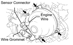
19. REMOVE NO. 3 TIMING BELT COVER SUB-ASSEMBLY LH
|
(a) Disconnect the engine wire from the 2 wire clamps. |
|
(b) Disconnect the camshaft position sensor connector.
(c) Disconnect the camshaft position sensor wire from the wire clamp on the timing belt cover.
(d) Remove the wire grommet from the timing belt cover.
(e) Remove the 4 bolts.
(f) Disconnect the timing belt cover from the timing plate and camshaft bearing cap.
(g) Disconnect the wire clamp for the sensor from the timing belt cover.
(h) Remove the connector holder from the sensor connector.
(i) Remove the timing belt cover.
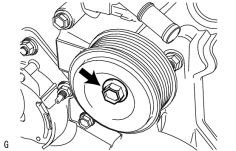
20. REMOVE NO. 2 IDLER PULLEY SUB-ASSEMBLY
|
(a) Remove the pulley bolt, cover plate and idler pulley. |
|
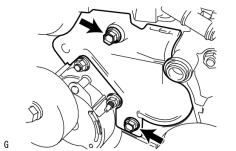
21. REMOVE NO. 2 TIMING BELT COVER SUB-ASSEMBLY
|
(a) Remove the 2 bolts and timing belt cover. |
|
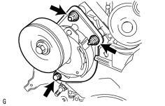
22. REMOVE DRIVE BELT TENSIONER ASSEMBLY
|
(a) Remove the bolt, 2 nuts and belt tensioner. |
|
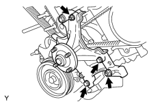
23. REMOVE IDLER PULLEY ASSEMBLY
|
(a) Remove the 2 bolts, 2 nuts and idler pulley. |
|
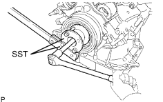
24. REMOVE CRANKSHAFT DAMPER SUB-ASSEMBLY
|
(a) Using SST, remove the damper bolt. SST: 09213-70011 09213-70020 SST: 09330-00021 |
|
|
(b) Using SST, remove the damper. SST: 09950-50013 09951-05010 09952-05010 09953-05010 09953-05020 09954-05021 |
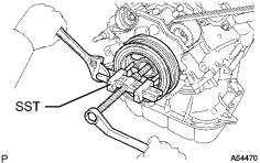
|
25. REMOVE NO. 1 TIMING BELT COVER
|
(a) Remove the 4 bolts and cover. |
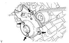
|
26. REMOVE CRANKSHAFT POSITION SENSOR PLATE
27. REMOVE TIMING BELT
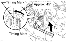
(a) Set the No. 1 cylinder to approximately 45° BTDC/compression.
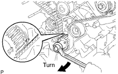
(1) Using the crankshaft damper bolt, turn the crankshaft to align the timing marks of the crankshaft timing pulley and oil pump body.
|
(2) Check that the timing marks of the camshaft timing pulleys and timing belt plates are aligned.
|
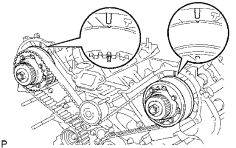
|
|
(3) Using the crankshaft damper bolt, turn the crankshaft counterclockwise by approximately 45°. NOTICE: If the timing belt is disengaged, having the crankshaft pulley at a wrong angle can cause the piston head and valve head to come into contact with each other when removing the camshaft timing pulley and camshaft, causing damage. So always set the crankshaft pulley at the correct angle. |
|
|
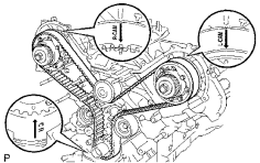
(b) If planning to reuse the belt, check the installation marks on the timing belt. (1) Check that there are 3 installation marks on the belt by turning the crankshaft as shown in the illustration.
|
|
|
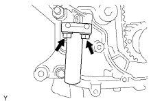
(c) Alternately loosen the 2 bolts. Then remove the 2 bolts, belt tensioner and dust boot. |
|
|
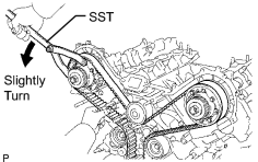
(d) Using SST, loosen the tension between the camshaft timing pulley (RH) and crankshaft timing pulley by slightly turning the camshaft timing pulley (RH) counterclockwise. SST: 09960-10010 09962-01000 09963-00350 |
|
(e) Disconnect the belt from the No. 1 timing belt idler, and remove the belt.

|

|