| Last Modified: 4-30-2014 | 6.6 G | Doc ID: RM000000SLX007X |
| Model Year: 2006 | Model: LX470 | Prod Date Range: [05/2005 - ] |
| Title: 2UZ-FE ENGINE MECHANICAL: CYLINDER HEAD: INSPECTION; 2006 MY LX470 [05/2005 - ] | ||
INSPECTION
1. INSPECT CYLINDER HEAD SUB-ASSEMBLY
(a) Clean the cylinder head.
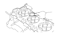
(1) Using a gasket scraper, remove all the gasket material from the cylinder block contact surface.
NOTICE:
Be careful not to scratch the cylinder block contact surface.
|
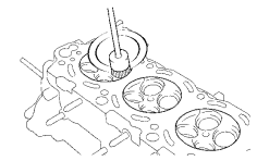
(2) Using a wire brush, remove all the carbon from the combustion chambers. NOTICE: Be careful not to scratch the cylinder block contact surface. |
|
|
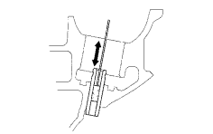
(3) Using a valve guide bushing brush and solvent, clean all the guide bushes. |
|
|
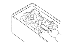
(4) Using a soft brush and solvent, thoroughly clean the cylinder head. |
|
|
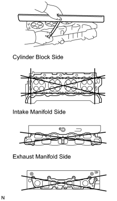
(b) Inspect for flatness. (1) Using a precision straightedge and feeler gauge, measure the surfaces contacting the cylinder block and the manifolds for warpage. Maximum warpage:
If the warpage is greater than the maximum, replace the cylinder head. |
|
|
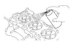
(c) Inspect the cylinder head for cracks. (1) Using a dye penetrant, check the combustion chamber, intake ports, exhaust ports and cylinder block surface for cracks.
|
|
2. REMOVE EXHAUST MANIFOLD SUB-ASSEMBLY LH
|
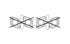
(a) Using a precision straightedge and feeler gauge, measure the surface contacting the cylinder head for warpage. Maximum warpage: 0.50 mm (0.0197 in.) If the warpage is greater than the maximum, replace the manifold. |
|
3. REMOVE EXHAUST MANIFOLD SUB-ASSEMBLY RH
|
(a) Using a precision straightedge and feeler gauge, measure the surface contacting the cylinder head for warpage. Maximum warpage: 0.50 mm (0.0197 in.) If the warpage is greater than the maximum, replace the manifold. |
|
4. INSPECT INTAKE VALVE GUIDE BUSH
|
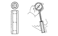
(a) Using a caliper gauge, measure the inside diameter of the guide bush. Standard bush inside diameter: 5.510 to 5.530 mm (0.2169 to 0.2177 in.)
|
|
(b) Subtract the valve stem diameter measurement from the guide bush inside diameter measurement.
Standard oil clearance:
0.025 to 0.060 mm (0.0010 to 0.0024 in.)
Maximum oil clearance:
0.08 mm (0.0031 in.)
- If the clearance is greater than the maximum, replace the valve and guide bush.
5. INSPECT EXHAUST VALVE GUIDE BUSH
|
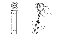
(a) Using a caliper gauge, measure the inside diameter of the guide bush. Standard bush inside diameter: 5.510 to 5.530 mm (0.2169 to 0.2177 in.)
|
|
(b) Subtract the valve stem diameter measurement from the guide bush inside diameter measurement.
Standard oil clearance:
0.030 to 0.065 mm (0.0012 to 0.0026 in.)
Maximum oil clearance:
0.10 mm (0.0039 in.)
- If the clearance is greater than the maximum, replace the valve and guide bush.
6. INSPECT INTAKE VALVE
|
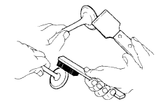
(a) Clean the valves. (1) Using a gasket scraper, chip off any carbon from the valve head. (2) Using a wire brush, thoroughly clean the valve. |
|
|
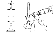
(b) Using a micrometer, measure the diameter of the valve stem. Standard valve stem diameter: 5.470 to 5.485 mm (0.2154 to 0.2159 in.)
|
|
|
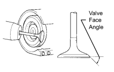
(c) Check the valve face angle. (1) Grind the valve sufficiently to remove pits and carbon. (2) Check that the valve is ground to the correct valve face angle. Standard valve face angle: 44.5°
|
|
|
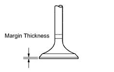
(d) Check the valve head margin thickness. Standard margin thickness: 1.00 mm (0.039 in.) Minimum margin thickness: 0.5 mm (0.020 in.)
|
|
|
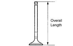
(e) Check the valve overall length. Standard overall length: 95.05 mm (3.7421 in.) Minimum overall length: 94.55 mm (3.7224 in.)
|
|
|
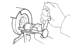
(f) Check the surface of the valve stem tip for wear.
|
|
7. INSPECT EXHAUST VALVE
|
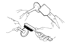
(a) Clean the valves. (1) Using a gasket scraper, chip off any carbon from the valve head. (2) Using a wire brush, thoroughly clean the valve. |
|
|
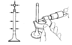
(b) Using a micrometer, measure the diameter of the valve stem. Standard valve stem diameter: 5.465 to 5.480 mm (0.2152 to 0.2157 in.)
|
|
|
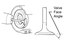
(c) Check the valve face angle. (1) Grind the valve sufficiently to remove pits and carbon. (2) Check that the valve is ground to the correct valve face angle. Standard valve face angle: 44.5°
|
|
|
(d) Check the valve head margin thickness. Standard margin thickness: 1.0 mm (0.039 in.) Minimum margin thickness: 0.5 mm (0.020 in.)
|
|
|
(e) Check the overall valve length. Standard overall length: 95.10 mm (3.7441 in.) Minimum overall length: 94.60 mm (3.7244 in.)
|
|
|
(f) Check the surface of the valve stem tip for wear.
|
|
8. INSPECT VALVE SPRING
|
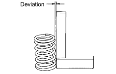
(a) Using steel squares, measure the deviation of the spring. Maximum deviation: 2.0 mm (0.079 in.)
|
|
|
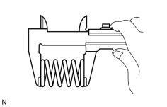
(b) Using a vernier caliper, measure the free length of the spring. Standard free length: 54.1 mm (2.130 in.)
|
|
|
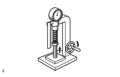
(c) Using a spring tester, measure the tension of the valve spring at the specified installed length. Standard installed tension: 210 to 226 N (21.4 to 23.0 kgf, 47.2 to 50.7 lbf) at 35.0 mm (1.378 in.)
|
|
9. INSPECT INTAKE VALVE SEAT
|
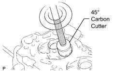
(a) Using a 45° carbon cutter, resurface the valve seats. HINT: Only remove the amount of metal necessary to clean the seats. |
|
|
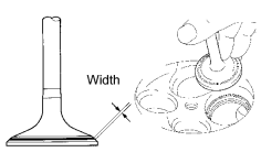
(b) Check the valve seating position. (1) Apply a light coat of Prussian blue (or white lead) to the valve face. (2) Lightly press the valve against the seat. Do not rotate the valve. |
|
(c) Check the valve face and seat for the following:
(1) If blue appears 360° around the face, the valve is concentric. If not, replace the valve.
(2) If blue appears 360° around the valve seat, the guide and face are concentric. If not, resurface the seat.
(3) Check that the seat contact is in the middle of the valve face and has the following width.
Standard width:
1.0 to 1.4 mm (0.039 to 0.055 in.)
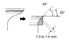
- If not, correct the intake valve seats as follows:
(d) If the seating is too high on the valve face:
- Use 30° and 45° cutters to correct the seat.
|
(e) If the seating is too low on the valve face:
|
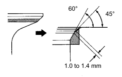
|
|
(f) Handrub the valve and valve seat with an abrasive compound. |
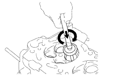
|
(g) After handrubbing, clean the valve and valve seat.
10. INSPECT EXHAUST VALVE SEAT
|
(a) Using a 45° carbon cutter, resurface the valve seats. HINT: Only remove the amount of metal necessary to clean the seats. |
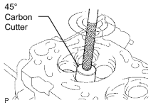
|
|
(b) Check the valve seating position. (1) Apply a light coat of Prussian blue (or white lead) to the valve face. (2) Lightly press the valve against the seat. Do not rotate the valve. |
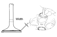
|
(c) Check the valve face and seat for the following:
(1) If blue appears 360° around the face, the valve is concentric. If not, replace the valve.
(2) If blue appears 360° around the valve seat, the guide and face are concentric. If not, resurface the seat.
(3) Check that the seat contact is in the middle of the valve face and has the following width.
Standard width:
1.0 to 1.4 mm (0.039 to 0.055 in.)
- If not, correct the exhaust valve seats as follows:
(d) If the seating is too high on the valve face:
- Use 30° and 45° cutters to correct the seat.
|
(e) If the seating is too low on the valve face:
|
|
|
(f) Handrub the valve and valve seat with an abrasive compound. |
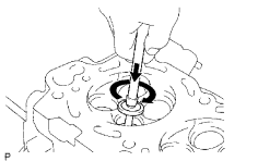
|
(g) After handrubbing, clean the valve and valve seat.
11. INSPECT VALVE LIFTER
|
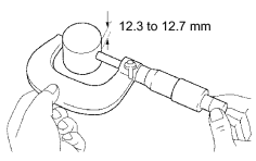
(a) Using a micrometer, measure the lifter diameter at a position 12.3 to 12.7 mm (0.484 to 0.500 in.) from the top surface. Standard lifter diameter: 30.968 to 30.976 mm (1.2192 to 1.2195 in.)
|
|
|
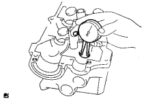
(b) Using a caliper gauge, measure the lifter bore diameter of the cylinder head. Standard lifter bore diameter: 31.000 to 31.016 mm (1.2205 to 1.2211 in.)
|
|
(c) Subtract the lifter diameter measurement from the lifter bore diameter measurement.
Standard oil clearance:
0.024 to 0.050 mm (0.0009 to 0.0020 in.)
Maximum oil clearance:
0.07 mm (0.0028 in.)
- If the oil clearance is greater than the maximum, replace the lifter. If necessary, replace the cylinder head.
12. INSPECT NO. 1 CAMSHAFT
|
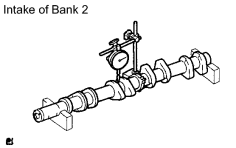
(a) Inspect the circle runout. (1) Place the camshaft on V-blocks. (2) Using a dial indicator, measure the circle runout at the center journal. Maximum circle runout: 0.03 mm (0.0012 in.)
|
|
|
(b) Using a micrometer, measure the cam lobe height. Standard cam lobe height: 42.61 to 42.71 mm (1.6776 to 1.6815 in.) Minimum cam lobe height: 42.46 mm (1.6717 in.)
|
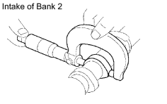
|
(c) Inspect the journal diameter of the camshaft.
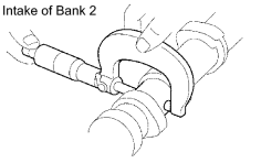
(1) Using a micrometer, measure the journal diameter of the camshaft for the camshaft bearing.
Standard journal diameter:
26.954 to 26.970 mm (1.0612 to 1.0618 in.)
- If the journal diameter is not as specified, check the oil clearance.
|
(2) Using a micrometer, measure the journal diameter for the camshaft timing tube. Standard journal diameter: 30.984 to 31.000 mm (1.2198 to 1.2205 in.)
|
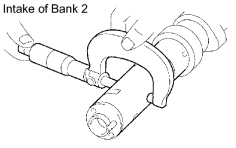
|
|
(d) Inspect the journal diameter of the camshaft timing tube. (1) Using a micrometer, measure the journal diameter. Standard journal diameter: 39.955 to 39.964 mm (1.5730 to 1.5734 in.)
(2) Install the drive gear to the camshaft timing tube. |
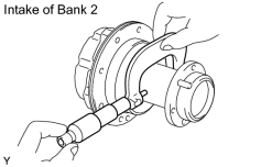
|
|
(e) Install the camshaft timing tube to the camshaft, and check that the timing tube turns smoothly.
|
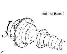
|
(f) Check the oil clearance.
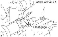
(1) Clean the bearing caps and journals.
(2) Check the bearings for flaking and scoring.
- If the bearings are damaged, replace the bearing caps and cylinder head as a set.
(3) Place the No. 1 camshaft on the cylinder head.
(4) Lay a strip of Plastigage across each of the journals.
(5) Install the bearing caps.
NOTICE:
Be careful not to turn the No. 1 camshaft.
(6) Remove the bearing caps.
|
(7) Measure the Plastigage at its widest point. Standard oil clearance:
Maximum oil clearance:
|
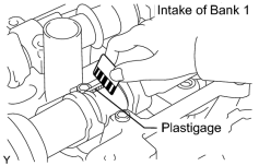
|
(8) Completely remove the Plastigage.
(9) Remove the camshaft.
|
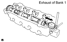
(g) Check the thrust clearance. (1) Install the camshaft. (2) Using a dial indicator, measure the thrust clearance while moving the camshaft back and forth. Standard thrust clearance: 0 to 0.040 mm (0 to 0.0016 in.) Maximum thrust clearance: 0.12 mm (0.0047 in.)
(3) Remove the camshaft. |
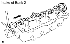
|
|
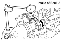
(h) Check the gear backlash. (1) Install the No. 1 camshaft and No. 2 camshaft without installing the camshaft sub-gear and front bearing cap. (2) Using a dial indicator, measure the backlash. Standard backlash: 0.020 to 0.200 mm (0.0008 to 0.0079 in.) Maximum backlash: 0.30 mm (0.0118 in.)
|
|
(i) Remove the No. 1 camshaft and No. 2 camshaft.
(j) Remove the camshaft timing tube from the camshaft.
(k) Remove the drive gear from the camshaft timing tube.
13. INSPECT NO. 2 CAMSHAFT
|
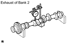
(a) Inspect the circle runout. (1) Place the camshaft on V-blocks. (2) Using a dial indicator, measure the circle runout at the center journal. Maximum circle runout: 0.03 mm (0.0012 in.)
|
|
|
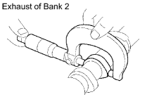
(b) Using a micrometer, measure the cam lobe height. Standard cam lobe height: 42.63 to 42.73 mm (1.6783 to 1.6822 in.) Minimum cam lobe height: 42.48 mm (1.6724 in.)
|
|
|
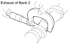
(c) Using a micrometer, measure the journal diameter. Standard journal diameter: 26.954 to 26.970 mm (1.0612 to 1.0618 in.)
|
|
(d) Check the oil clearance.
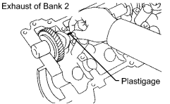
(1) Clean the bearing caps and journals.
(2) Check the bearings for flaking and scoring.
- If the bearings are damaged, replace the bearing caps and cylinder head as a set.
(3) Place the No. 2 camshaft on the cylinder head.
(4) Lay a strip of Plastigage across each of the journals.
(5) Install the bearing caps.
NOTICE:
Be careful not to turn the No. 2 camshaft.
(6) Remove the bearing caps.
|
(7) Measure the Plastigage at its widest point. Standard oil clearance: 0.030 to 0.071 mm (0.0012 to 0.0028 in.) Maximum oil clearance: 0.100 mm (0.0039 in.)
|
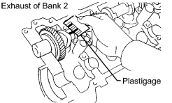
|
(8) Completely remove the Plastigage.
(9) Remove the No. 2 camshaft.
|
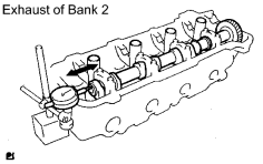
(e) Check the thrust clearance. (1) Install the No. 2 camshaft. (2) Using a dial indicator, measure the thrust clearance while moving the camshaft back and forth. Standard thrust clearance: 0.030 to 0.070 mm (0.0012 to 0.0028 in.) Maximum thrust clearance: 0.10 mm (0.0039 in.)
(3) Remove the No. 2 camshaft. |
|
14. INSPECT NO. 3 CAMSHAFT SUB-ASSEMBLY
|
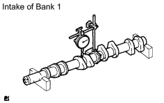
(a) Inspect the circle runout. (1) Place the camshaft on V-blocks. (2) Using a dial indicator, measure the circle runout at the center journal. Maximum circle runout: 0.03 mm (0.0012 in.)
|
|
|
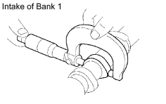
(b) Using a micrometer, measure the cam lobe height. Standard cam lobe height: 42.61 to 42.71 mm (1.6776 to 1.6815 in.) Minimum cam lobe height: 42.46 mm (1.6717 in.)
|
|
(c) Inspect the journal diameter of the No. 3 camshaft.
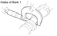
(1) Using a micrometer, measure the journal diameter of the No. 3 camshaft for the camshaft bearing.
Standard journal diameter:
26.954 to 26.970 mm (1.0612 to 1.0618 in.)
- If the journal diameter is not as specified, check the oil clearance.
|
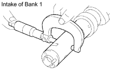
(2) Using a micrometer, measure the journal diameter for the camshaft timing tube. Standard journal diameter: 30.984 to 31.000 mm (1.2198 to 1.2205 in.)
|
|
|
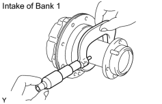
(d) Inspect the journal diameter of the camshaft timing tube. (1) Using a micrometer, measure the journal diameter. Standard journal diameter: 39.955 to 39.964 mm (1.5730 to 1.5734 in.)
(2) Install the drive gear to the camshaft timing tube. |
|
|
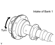
(e) Install the timing tube to the No. 3 camshaft, and check that the timing tube turns smoothly.
|
|
(f) Check the oil clearance.
(1) Clean the bearing caps and journals.
(2) Check the bearings for flaking and scoring.
- If the bearings are damaged, replace the bearing caps and cylinder head as a set.
(3) Place the No. 3 camshaft on the cylinder head.
(4) Lay a strip of Plastigage across each of the journals.
(5) Install the bearing caps.
NOTICE:
Be careful not to turn the camshaft.
(6) Remove the bearing caps.
|
(7) Measure the Plastigage at its widest point. Standard oil clearance:
Maximum oil clearance:
|
|
(8) Completely remove the Plastigage.
(9) Remove the No. 3 camshaft.
|
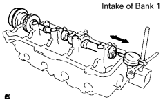
(g) Check the thrust clearance. (1) Install the No. 3 camshaft. (2) Using a dial indicator, measure the thrust clearance while moving the No. 3 camshaft back and forth. Standard thrust clearance: 0 to 0.040 mm (0 to 0.0016 in.) Maximum thrust clearance: 0.12 mm (0.0047 in.)
(3) Remove the No. 3 camshaft. |
|
|
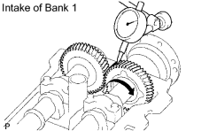
(h) Check the gear backlash. (1) Install the No. 3 camshaft and No. 4 camshaft without installing the camshaft sub-gear and front bearing cap. (2) Using a dial indicator, measure the backlash. Standard backlash: 0.020 to 0.200 mm (0.0008 to 0.0079 in.) Maximum backlash: 0.30 mm (0.0118 in.)
|
|
(i) Remove the No. 3 camshaft and No. 4 camshaft.
(j) Remove the camshaft timing tube from the No. 3 camshaft.
(k) Remove the drive gear from the camshaft timing tube.
15. INSPECT NO. 4 CAMSHAFT SUB-ASSEMBLY
|
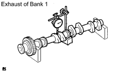
(a) Inspect the circle runout. (1) Place the camshaft on V-blocks. (2) Using a dial indicator, measure the circle runout at the center journal. Maximum circle runout: 0.03 mm (0.0012 in.)
|
|
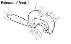
|
(b) Using a micrometer, measure the cam lobe height. Standard cam lobe height: 42.63 to 42.73 mm (1.6783 to 1.6822 in.) Minimum cam lobe height: 42.48 mm (1.6724 in.)
|
|
|
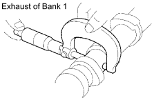
(c) Using a micrometer, measure the journal diameter. Standard journal diameter: 26.954 to 26.970 mm (1.0612 to 1.0618 in.)
|
|
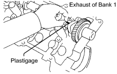
(d) Check the oil clearance.
(1) Clean the bearing caps and journals.
(2) Check the bearings for flaking and scoring.
- If the bearings are damaged, replace the bearing caps and cylinder head as a set.
(3) Place the No. 4 camshaft on the cylinder head.
(4) Lay a strip of Plastigage across each of the journals.
(5) Install the bearing caps.
NOTICE:
Be careful not to turn the No. 4 camshaft.
(6) Remove the bearing caps.
|
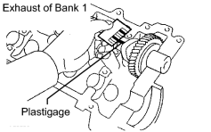
(7) Measure the Plastigage at its widest point. Standard oil clearance: 0.030 to 0.071 mm (0.0012 to 0.0028 in.) Maximum oil clearance: 0.100 mm (0.0039 in.)
|
|
(8) Completely remove the Plastigage.
(9) Remove the No. 4 camshaft.
|
(e) Check the thrust clearance. (1) Install the No. 4 camshaft. (2) Using a dial indicator, measure the thrust clearance while moving the No. 4 camshaft back and forth. Standard thrust clearance: 0.030 to 0.070 mm (0.0012 to 0.0028 in.) Maximum thrust clearance: 0.10 mm (0.0039 in.)
(3) Remove the No. 4 camshaft. |
|
16. INSPECT CYLINDER HEAD SET BOLT
|
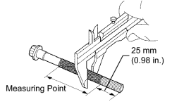
(a) Using a vernier caliper, measure the thread outside diameter of the bolt. Standard outside diameter: 9.810 to 9.960 mm (0.3862 to 0.3921 in.) Minimum outside diameter: 9.70 mm (0.3819 in.)
|
|

|

|