| Last Modified: 4-30-2014 | 6.6 A | Doc ID: RM000000SM0007X |
| Model Year: 2006 | Model: LX470 | Prod Date Range: [05/2005 - ] |
| Title: 2UZ-FE ENGINE MECHANICAL: CYLINDER HEAD: DISASSEMBLY; 2006 MY LX470 [05/2005 - ] | ||
DISASSEMBLY
1. REMOVE VALVE LIFTER
(a) Remove the valve lifter and adjusting shim.
HINT:
Arrange the valve lifters and shims in the correct order.
2. REMOVE INTAKE VALVE
|
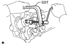
(a) Using SST, compress the valve spring and remove the 2 valve spring retainer locks. SST: 09202-70020 09202-00010 |
|
(b) Remove the spring retainer, valve spring, valve and spring seat.
HINT:
Arrange the valves, valve springs, spring seats and spring retainers in the correct order.
3. REMOVE EXHAUST VALVE
|
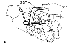
(a) Using SST, compress the valve spring and remove the 2 valve spring retainer locks. SST: 09202-70020 09202-00010 |
|
(b) Remove the spring retainer, valve spring, valve and spring seat.
HINT:
Arrange the valves, valve springs, spring seats and spring retainers in the correct order.
4. REMOVE VALVE STEM OIL SEAL
|
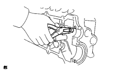
(a) Using needle nose pliers, remove the oil seal. |
|
5. REMOVE CAMSHAFT TIMING TUBE ASSEMBLY
|
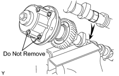
(a) Mount the hexagon head portion of the camshaft in a vise. NOTICE:
|
|
(b) Remove the screw plug and seal washer.
|
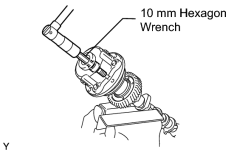
(c) Using a 10 mm hexagon wrench, remove the bolt. |
|
(d) Pull out the timing tube and drive gear from the camshaft.
|
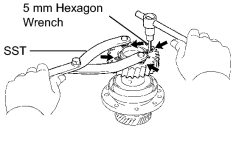
(e) Using SST and a 5 mm hexagon wrench, remove the 4 bolts, drive gear and oil seal. SST: 09960-10010 09962-01000 09963-00500 NOTICE: Be careful not to damage the timing tube. |
|
6. REMOVE CAMSHAFT SUB GEAR
|
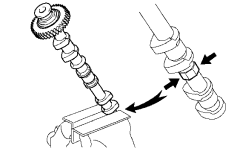
(a) Mount the hexagon head portion of the camshaft in a vise. NOTICE: Be careful not to damage the camshaft. |
|
|
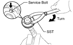
(b) Using SST, turn the sub-gear clockwise and remove the service bolt. SST: 09960-10010 09962-01000 09963-00500 Recommended service bolt:
|
|
|
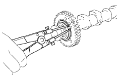
(c) Using snap ring pliers, remove the snap ring. |
|
(d) Remove the wave washer, sub-gear and bolt washer.
HINT:
Arrange the driven sub-gears and bolt washers (bank 2 and bank 1).
|
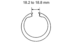
(e) Using a vernier caliper, measure the free distance between the washer ends. Standard free distance: 18.2 to 18.8 mm (0.712 to 0.740 in.) If the free distance is not as specified, replace the washer. |
|

|

|