| Last Modified: 4-30-2014 | 6.6 A | Doc ID: RM000000SMJ006X |
| Model Year: 2006 | Model: LX470 | Prod Date Range: [05/2005 - ] |
| Title: 2UZ-FE ENGINE MECHANICAL: ENGINE UNIT: REASSEMBLY; 2006 MY LX470 [05/2005 - ] | ||
REASSEMBLY
HINT:
- Thoroughly clean all parts to be assembled.
- Before installing the parts, apply new engine oil to all sliding and rotating surfaces.
- Replace all gaskets, O-rings and oil seals with new parts.
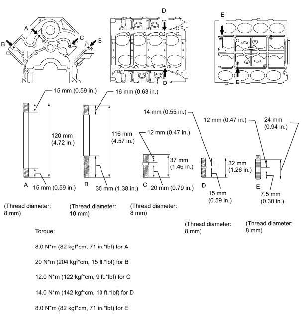
1. INSTALL STUD BOLT
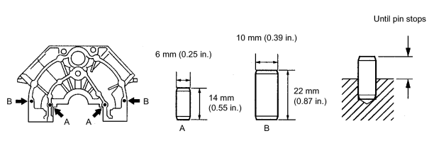
2. INSTALL STRAIGHT PIN
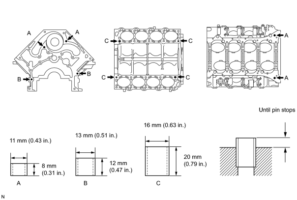
3. INSTALL RING PIN
4. INSTALL PISTON SUB-ASSEMBLY WITH PIN
|
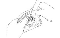
(a) Using a small screwdriver, install a new snap ring on one side of the piston pin hole. |
|
|
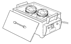
(b) Gradually heat the piston to about 60°C (140°F). |
|
|
(c) Coat the piston pin with engine oil. |
|
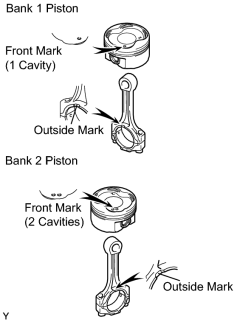
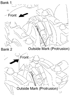
(d) The piston's front mark and the connecting rod's outside mark should face the same direction, as shown in the illustration.
NOTICE:
The installation directions of the piston and connecting rod are different for the bank 1 and bank 2. The bank 1 piston is marked with 1 cavity and "LH", the bank 2 piston with 2 cavities and "RH".
(e) Align the piston pin holes of the piston and connecting rod, and push in the piston pin with your thumb.
|
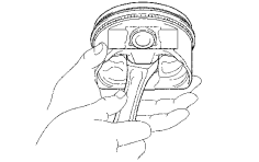
(f) Check the fit between the piston and piston pin. (1) Try to move the piston back and forth on the piston pin. |
|
|
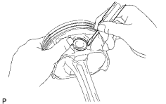
(g) Using a small screwdriver, install a new snap ring on the other side of the piston pin hole. |
|
(h) Install the oil ring expander and 2 side rails by hand.
|
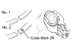
(i) Using a piston ring expander, install the No. 1 and No. 2 piston rings with the code mark facing upward. Code mark:
|
|
(j) Position the piston rings so that the ring ends are as shown in the illustration.
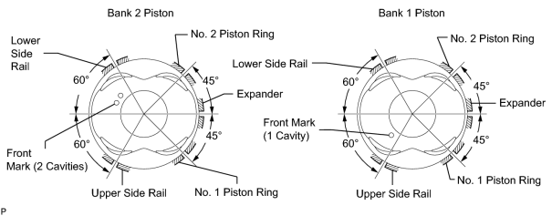
NOTICE:
Do not align the ring ends.
5. INSTALL CONNECTING ROD BEARING
|
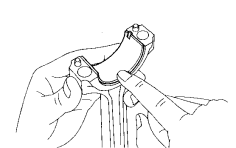
(a) Align the bearing claw with the groove of the connecting rod or connecting cap. |
|
(b) Install the bearings in the connecting rod and connecting rod cap.
6. INSTALL CRANKSHAFT BEARING
HINT:
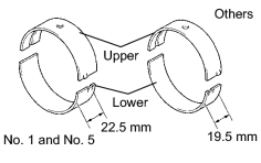
- Main bearings come in widths of 19.5 mm (0.768 in.) and 22.5 mm (0.886 in.). Install the 22.5 mm (0.886 in.) bearings in the No. 1 and No. 5 cylinder block journal positions with the crankshaft bearing cap. Install the 19.5 mm (0.768 in.) bearings in the other positions.
- Upper bearings have an oil groove and oil holes; lower bearings do not.
|
(a) Align the bearing claw with the claw groove of the cylinder block, and push in the 5 upper bearings. |
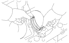
|
|
(b) Align the bearing claw with the claw groove of the crankshaft bearing cap, and push in the 5 lower bearings. HINT: A number is marked on each bearing cap to indicate the installation position. |
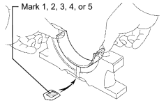
|
7. INSTALL CRANKSHAFT THRUST WASHER SET
|
(a) Install the 2 thrust washers under the No. 3 journal position of the cylinder block with the oil grooves facing outward. |
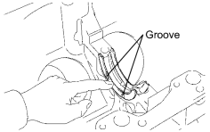
|
|
(b) Install the 2 thrust washers on the No. 3 bearing cap with the grooves facing outward. |
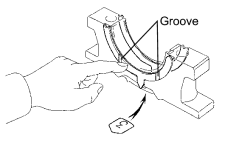
|
8. INSTALL CRANKSHAFT
|
(a) Place the crankshaft on the cylinder block. |
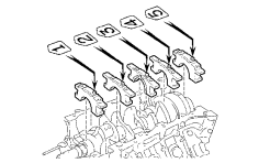
|
(b) Install the 5 crankshaft bearing caps in their proper locations.
HINT:
Place the bearing caps on the level and let them return to their original positions by their own weight.
NOTICE:
Do not install the bearing cap by tapping it.
(c) Install the crankshaft bearing cap bolts.
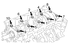
HINT:
If any one of the bearing cap bolts is broken or deformed, replace it.
(1) Apply a light coat of engine oil on the threads and under the crankshaft bearing cap bolts.
(2) Install and uniformly tighten the 10 crankshaft bearing cap bolts in several passes in the sequence shown in the illustration.
Torque:
27 N·m {275 kgf·cm, 20ft·lbf}
If any of the bearing cap bolts cannot meet the torque specification, replace the bearing cap bolt.
|
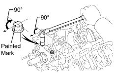
(3) Mark the front of the crankshaft bearing cap bolt's head with paint. |
|
(4) Tighten the crankshaft bearing cap bolts another 90° as shown in the illustration.
(5) Check that the painted mark is now at a 90° angle to the front.
(d) Check that the crankshaft turns smoothly.
9.
CHECK CRANKSHAFT THRUST CLEARANCE
![2006 MY LX470 [05/2005 - ]; 2UZ-FE ENGINE MECHANICAL: ENGINE UNIT: DISASSEMBLY+](../../../../stylegraphics/info.gif "2006 MY LX470 [05/2005 - ]; 2UZ-FE ENGINE MECHANICAL: ENGINE UNIT: DISASSEMBLY+")
10. INSTALL PISTON AND CONNECTING ROD
|
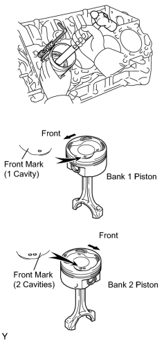
(a) Using a piston ring compressor, push the correctly numbered piston and connecting rod assemblies into each cylinder with the front mark of the piston facing forward. NOTICE: The shape of the piston varies for the bank 1 and bank 2. The bank 1 piston is marked with 1 cavity and "LH" the bank 2 piston with 2 cavities and "RH". |
|
(b) Place the connecting rod cap on the connecting rod.
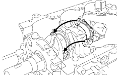
(1) Match the numbered connecting rod cap with the connecting rod.
(2) Align the pin groove of the connecting rod cap with the pins of the connecting rod, and install the connecting rod cap.
|
(3) Check that the outside mark of the connecting rod cap is facing in the correct direction. |
|
(c) Install the connecting rod cap bolts.
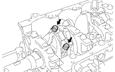
HINT:
If any one of the connecting rod cap bolts is broken or deformed, replace it.
(1) Apply a light coat of engine oil on the threads and under the heads of the connecting rod cap bolts.
(2) Install and alternately tighten the 2 connecting rod cap bolts in several passes.
Torque:
24.5 N·m {250 kgf·cm, 18ft·lbf}
If any of the connecting rod cap bolts cannot meet the torque specification, replace the connecting rod cap bolts.
|
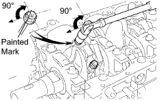
(3) Mark the front of the connecting cap bolt with paint. |
|
(4) Tighten the cap bolts another 90° as shown in the illustration.
(5) Check that the painted mark is now at a 90° angle to the front.
(d) Check that the crankshaft turns smoothly.
11.
CHECK CONNECTING ROD THRUST CLEARANCE
12. INSTALL CYLINDER BLOCK WATER DRAIN COCK SUB-ASSEMBLY
|
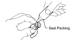
(a) Apply seal packing to 2 or 3 threads of the drain cocks. Seal packing: Toyota Genuine Seal Packing 1282B, Three Bond 1282B or Equivalent |
|
|
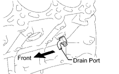
(b) Install the 2 drain cocks. Torque: 49 N·m {500 kgf·cm, 36ft·lbf} HINT: After applying the specified torque, rotate the drain union clockwise until its drain port is facing forward. |
|
13. INSTALL REAR OIL SEAL RETAINER
(a) Remove any old seal packing material, and be careful not to drop any oil on the contact surfaces of the oil seal retainer and the cylinder block.
(1) Using a razor blade and a gasket scraper, remove old seal packing from the seal surface.
(2) Clean all the components to remove the redundant seal packing completely.
(3) Clean sealing surfaces with solvent so that any residue does not remain on the seal.
|
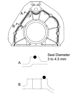
(b) Apply seal packing to the oil seal retainer as shown in the illustration. Seal packing: Toyota Genuine Seal Packing Black, Three Bond 1207B or Equivalent Standard seal diameter: 3 to 4.5 mm (0.12 to 0.18 in.) NOTICE:
|
|
|
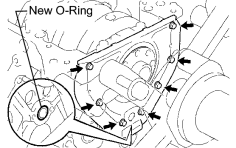
(c) Install a new O-ring to the cylinder block. |
|
(d) Install the oil seal retainer with the 7 bolts.
Torque:
8.0 N·m {82 kgf·cm, 71in·lbf}
14.
INSTALL OIL PUMP ASSEMBLY
15.
INSTALL OIL STRAINER SUB-ASSEMBLY
16. INSTALL OIL PAN STUD BOLT
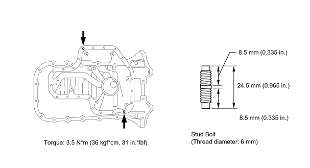
17.
INSTALL NO. 1 OIL PAN SUB-ASSEMBLY
18.
INSTALL OIL PAN BAFFLE PLATE NO.1
19.
INSTALL NO. 2 OIL PAN SUB-ASSEMBLY
20.
INSTALL WATER PUMP ASSEMBLY
21. INSTALL CYLINDER HEAD SUB-ASSEMBLY
(a)
Install the cylinder head
.
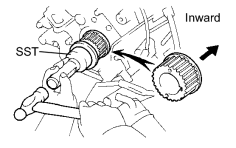
22. INSTALL CRANKSHAFT TIMING PULLEY
(a) Fit the timing pulley set key to the key groove of the pulley.
|
(b) Using SST and a hammer, tap in the timing pulley with the flange side facing inward. SST: 09223-46011 |
|
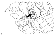
23. INSTALL NO. 2 TIMING BELT IDLER SUB-ASSEMBLY
|
(a) Install the idler with the bolt. Torque: 34.5 N·m {352 kgf·cm, 25ft·lbf} |
|
(b) Check that the idler moves smoothly.
24. INSTALL NO. 1 TIMING BELT IDLER SUB-ASSEMBLY
|
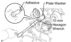
(a) Apply adhesive to 2 or 3 threads of the pivot bolt. Adhesive: Toyota Genuine Adhesive 1344, Three Bond 1344 or Equivalent |
|
(b) Using a 10 mm hexagon wrench, install the plate washer and idler with the pivot bolt.
Torque:
34.5 N·m {352 kgf·cm, 25ft·lbf}
(c) Check that the idler bracket moves smoothly.
25. INSTALL TIMING BELT
(a)
Install the timing belt
.

|

|