- Short in knock sensor 1 or 2 circuit
| Last Modified: 4-30-2014 | 6.6 C | Doc ID: RM000000SVT00AX |
| Model Year: 2006 | Model: LX470 | Prod Date Range: [05/2005 - ] |
| Title: 2UZ-FE ENGINE CONTROL SYSTEM: SFI SYSTEM: P0327,P0328,P0332,P0333; Knock Sensor 1 Circuit Low Input (Bank 1 or Single Sensor); 2006 MY LX470 [05/2005 - ] | ||
|
DTC |
P0327 |
Knock Sensor 1 Circuit Low Input (Bank 1 or Single Sensor) |
|
DTC |
P0328 |
Knock Sensor 1 Circuit High Input (Bank 1 or Single Sensor) |
|
DTC |
P0332 |
Knock Sensor 2 Circuit Low Input (Bank 2) |
|
DTC |
P0333 |
Knock Sensor 2 Circuit High Input (Bank 2) |
DESCRIPTION
A flat type knock sensor (non-resonant type) has a structure that can detect vibrations over a wide band of frequencies: between approximately 6 kHz and 15 kHz.
Knock sensors are fitted onto the engine block to detect engine knocking.
The knock sensor contains a piezoelectric element which generates a voltage when it becomes deformed.
The voltage is generated when the engine block vibrates due to knocking. Any occurrence of engine knocking can be suppressed by delaying the ignition timing.
|
DTC No. |
DTC Detection Condition |
Trouble Area |
|---|---|---|
|
P0327 P0332 |
Output voltage of knock sensor 1 or 2 is 0.5 V or less (1 trip detection logic) |
|
|
P0328 P0333 |
Output voltage of knock sensor 1 or 2 is 4.5 V or more (1 trip detection logic) |
|
HINT:
When any of DTCs P0327, P0328, P0332 and P0333 are set, the ECM enters fail-safe mode. During fail-safe mode, the ignition timing is delayed to its maximum retardation. Fail-safe mode continues until the ignition switch is turned OFF.
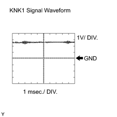
Reference: Inspect using an oscilloscope
The correct waveform is as shown.
|
Item |
Content |
|---|---|
|
Terminals |
KNK1 - EKNK or KNK2 -EKN2 |
|
Equipment Settings |
0.01 to 10 V/DIV. 0.01 to 10 msec./DIV. |
|
Conditions |
Keep engine speed at 4,000 rpm with warm engine |
MONITOR DESCRIPTION
The knock sensor, located on the cylinder block, detects spark knock. When spark knock occurs, the piezoelectric element of the sensor vibrates. When the ECM detects a voltage in this frequency range, it retards the ignition timing to suppress the spark knock.
The ECM also senses background engine noise with the knock sensor and uses this noise to check for faults in the sensor. If the knock sensor signal level is too low for more than 10 seconds, or if the knock sensor output voltage is outside the normal range, the ECM interprets this as a fault in the knock sensor and sets a DTC.
MONITOR STRATEGY
|
Related DTCs |
P0327: Knock sensor (Bank 1) open/short (Low voltage) P0328: Knock sensor (Bank 1) open/short (High voltage) P0332: Knock sensor (Bank 2) open/short (Low voltage) P0333: Knock sensor (Bank 2) open/short (High voltage) |
|
Required Sensors/Components (Main) |
Knock sensor (Bank 1 and 2) |
|
Required Sensors/Components (Related) |
- |
|
Frequency of Operation |
Continuous |
|
Duration |
1 second |
|
MIL Operation |
Immediate |
|
Sequence of Operation |
None |
TYPICAL ENABLING CONDITIONS
|
Monitor runs whenever following DTCs not present |
None |
|
Battery voltage |
10.5 V or more |
|
Time after engine start |
5 seconds or more |
TYPICAL MALFUNCTION THRESHOLDS
Knock Sensor Range Check (Low voltage) P0327 and P0332:
|
Knock sensor voltage |
Less than 0.5 V |
Knock Sensor Range Check (High voltage) P0328 and P0333:
|
Knock sensor voltage |
More than 4.5 V |
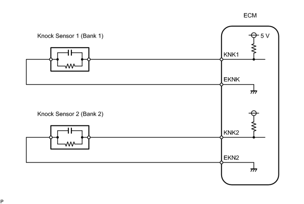
WIRING DIAGRAM
INSPECTION PROCEDURE
HINT:
- DTCs P0327 and P0328 are for the bank 1 knock sensor circuit.
- DTCs P0332 and P0333 are for the bank 2 knock sensor circuit.
- Read freeze frame data using the intelligent tester. Freeze frame data records the engine conditions when malfunctions are detected. When troubleshooting, freeze frame data can help determine if the vehicle was moving or stationary, if the engine was warmed up or not, if the air fuel ratio was lean or rich, and other data from the time the malfunction occurred.
PROCEDURE
|
1. |
READ OUTPUT DTC (CHECK KNOCK SENSOR CIRCUIT) |
|
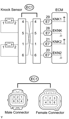
(a) Disconnect the EC1 connector. (b) Using lead wires, connect the EC1 connectors as follows.
(c) Warm up the engine. (d) Race the engine at 3,000 rpm for 10 seconds or more. (e) Check for DTCs.
|
|
| B |

|
|

|
2. |
CHECK HARNESS AND CONNECTOR (CONNECTOR - ECM) |
(a)
Check harness and connector
![2006 MY LX470 [05/2005 - ]; INTRODUCTION: HOW TO TROUBLESHOOT ECU CONTROLLED SYSTEMS: ELECTRONIC CIRCUIT INSPECTION PROCEDURE](../../../../stylegraphics/info.gif "2006 MY LX470 [05/2005 - ]; INTRODUCTION: HOW TO TROUBLESHOOT ECU CONTROLLED SYSTEMS: ELECTRONIC CIRCUIT INSPECTION PROCEDURE") .
.
| NG |
|
|
|
3. |
INSPECT ECM |
|
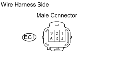
(a) Disconnect the EC1 connector. (b) Turn the ignition switch ON. (c) Measure the voltage of the EC1 male connector. Standard voltage:
|
|
| NG |
|
|
|
4. |
CHECK FOR INTERMITTENT PROBLEMS |
NOTICE:
The fault may be intermittent. Check the harness and connectors carefully, and reset.
| NEXT |
|
|
5. |
INSPECT KNOCK SENSOR |
|
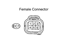
(a) Disconnect the EC1 connector. (b) Measure the resistance of the EC1 female connector. Standard resistance:
|
|
| OK |
|
|
|
6. |
CHECK HARNESS AND CONNECTOR (CONNECTOR - KNOCK SENSOR) |
(a)
Check harness and connector
.
| NG |
|
| OK |
|

|

|