- Open in back-up power source circuit
- EFI OR ECD NO. 1 fuse
- ECM
| Last Modified: 4-30-2014 | 6.6 C | Doc ID: RM000000T8P00NX |
| Model Year: 2006 | Model: LX470 | Prod Date Range: [05/2005 - ] |
| Title: 2UZ-FE ENGINE CONTROL SYSTEM: SFI SYSTEM: P0560; System Voltage; 2006 MY LX470 [05/2005 - ] | ||
|
DTC |
P0560 |
System Voltage |
MONITOR DESCRIPTION
The battery supplies electricity to the ECM even when the ignition switch is OFF. This electricity allows the ECM to store data such as DTC history, freeze frame data, fuel trim values, and other data. If the battery voltage falls below a minimum level, the memory is cleared and the ECM will conclude that there is a fault in the power supply circuit. At the next engine start, the ECM will illuminate the MIL and set a DTC.
|
DTC No. |
DTC Detection Condition |
Trouble Area |
|---|---|---|
|
P0560 |
Open in ECM back-up power source circuit |
|
HINT:
If DTC P0560 appears, the ECM does not store another DTC.
MONITOR STRATEGY
|
Related DTCs |
P0560: ECM system voltage |
|
Required Sensors/Components (Main) |
ECM |
|
Required Sensors/Components (Related) |
- |
|
Frequency of Operation |
Continuous |
|
Duration |
3 seconds |
|
MIL Operation |
Immediate (MIL will be illuminated after next engine start) |
|
Sequence of Operation |
None |
TYPICAL ENABLING CONDITIONS
|
Monitor will run whenever these DTCs are not present |
None |
|
Stand-by RAM |
Initialized |
TYPICAL MALFUNCTION THRESHOLDS
|
ECM power source |
Less than 3.5 V |
WIRING DIAGRAM
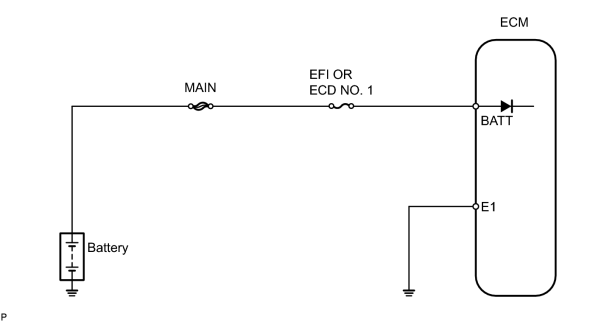
INSPECTION PROCEDURE
HINT:
Read freeze frame data using the intelligent tester. Freeze frame data records the engine conditions when malfunctions are detected. When troubleshooting, freeze frame data can help determine if the vehicle was running or stopped, if the engine was warmed up or not, if the air fuel ratio was lean or rich, and other data from the time the malfunction occurred.
PROCEDURE
|
1. |
READ VALUE USING INTELLIGENT TESTER (BATTERY VOLTAGE) |
(a) Connect the intelligent tester to the CAN VIM. Then connect the CAN VIM to the DLC3.
(b) Turn the ignition switch ON.
(c) Enter the following menus: DIAGNOSIS / ENHANCED OBD II / DATA LIST / PRIMARY / BATTERY VOLTAGE.
|
Battery voltage |
Proceed to |
|---|---|
|
Battery voltage is 0 V |
A |
|
Battery voltage is except 0 V |
B |
| B |

|
|

|
2. |
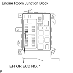
INSPECT FUSE (EFI OR ECD NO. 1) |
|
(a) Remove the EFI OR ECD NO. 1 fuse from the engine room junction block. (b) Measure the resistance of the fuse. Standard resistance: Below 1 Ω |
|
| NG |
|
CHECK FOR SHORT IN ALL HARNESS AND COMPONENTS CONNECTED TO FUSE |
|
|
3. |
CHECK HARNESS AND CONNECTOR (ECM - EFI OR ECD NO. 1 FUSE, EFI OR ECD NO. 1 FUSE - BATTERY) |
(a)
Check harness and connector
![2006 MY LX470 [05/2005 - ]; INTRODUCTION: HOW TO TROUBLESHOOT ECU CONTROLLED SYSTEMS: ELECTRONIC CIRCUIT INSPECTION PROCEDURE](../../../../stylegraphics/info.gif "2006 MY LX470 [05/2005 - ]; INTRODUCTION: HOW TO TROUBLESHOOT ECU CONTROLLED SYSTEMS: ELECTRONIC CIRCUIT INSPECTION PROCEDURE") .
.
| NG |
|
|
|
4. |
INSPECT BATTERY |
(a) Check that the battery is not depleted.
OK:
Battery voltage is 11 V or more.
| NG |
|
| OK |
|

|

|