- Open or short in engine wire harness
- Connector connection
- Vacuum hose connections
- Ignition system
- Fuel injector
- Fuel pressure
- Mass Air Flow (MAF) meter
- Engine Coolant Temperature (ECT) sensor
- Compression pressure
- Valve timing
- Valve clearance
- Ventilation valve and hose
- Ventilation hose connections
- ECM
| Last Modified: 4-30-2014 | 6.6 C | Doc ID: RM000000TL0008X |
| Model Year: 2006 | Model: LX470 | Prod Date Range: [05/2005 - ] |
| Title: 2UZ-FE ENGINE CONTROL SYSTEM: SFI SYSTEM: P0300-P0308; Random / Multiple Cylinder Misfire Detected; 2006 MY LX470 [05/2005 - ] | ||
|
DTC |
P0300 |
Random / Multiple Cylinder Misfire Detected |
|
DTC |
P0301 |
Cylinder 1 Misfire Detected |
|
DTC |
P0302 |
Cylinder 2 Misfire Detected |
|
DTC |
P0303 |
Cylinder 3 Misfire Detected |
|
DTC |
P0304 |
Cylinder 4 Misfire Detected |
|
DTC |
P0305 |
Cylinder 5 Misfire Detected |
|
DTC |
P0306 |
Cylinder 6 Misfire Detected |
|
DTC |
P0307 |
Cylinder 7 Misfire Detected |
|
DTC |
P0308 |
Cylinder 8 Misfire Detected |
DESCRIPTION
-
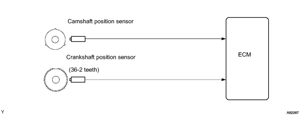
When a misfire occurs in the engine, hydrocarbons (HC) enter the exhaust in high concentrations. If the HC concentration is too high, exhaust emissions levels may increase. High concentrations of HC can also cause the temperature of the catalyst to increase, possibly damaging the catalyst. To prevent the increase in emissions and limit the possibility of thermal damage, the ECM monitors the misfire rate. When the temperature of the catalyst reaches a point of thermal degradation, the ECM will begin flashing the MIL. For monitoring misfires, the ECM uses both the Camshaft Position (CMP) sensor and the Crankshaft Position (CKP) sensor. The CMP sensor is used to identify misfiring cylinders and the CKP sensor is used to measure variations in the crankshaft rotation speed. The misfire counter records how many times the crankshaft rotation speed variations exceed threshold values.
If the misfiring rate exceeds the threshold value and could cause emissions to deteriorate, the ECM illuminates the MIL and sets a DTC.
|
DTC No. |
DTC Detection Condition |
Trouble Area |
|---|---|---|
|
P0300 |
Misfiring of random cylinder is detected |
|
|
P0301 P0302 P0303 P0304 P0305 P0306 P0307 P0308 |
Misfiring of each cylinder is detected |
Same as DTC No. P0300 |
HINT:
In some cases, several DTCs for misfired cylinders (DTCs P0301 to P0308) are recorded but the random/multiple cylinder misfire DTC (P0300) is not recorded. This is an indication that the misfires were detected and recorded at different times. Random misfire codes are recorded only when several misfires occur at the same time.
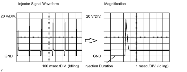
Reference: Inspect using an oscilloscope.
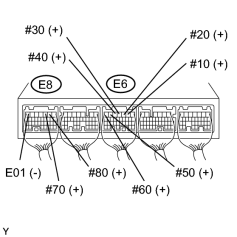
With the engine idling, check the waveform between terminals #10 to #80 and E1 of the ECM connectors.
The correct waveform is as shown.
MONITOR DESCRIPTION
The ECM illuminates the MIL as follows (2 trip detection logic is used and DTC is stored after 2 trip detection):
- The misfiring rate exceeds a threshold value and could cause emissions to deteriorate.
- During the first 1,000 crankshaft revolutions after engine starts, an excessive misfire rate (approximately 20 to 50 misfires per 1, 000 crankshaft revolutions) occurs once.
- An excessive misfire rate (approximately 20 to 60 times misfire per 1,000 crankshaft revolutions) occurs 4 times.
The ECM begins flashing the MIL as follows (2 trip detection logic is used and DTC is stored after 2 trip detection):
- Within 200 crankshaft revolutions at a high rpm, the threshold for "percent of misfires causing catalyst damage" is reached once.
- Within 200 crankshaft revolutions at a normal rpm, the threshold for "percent of misfires causing catalyst damage" is reached 3 times.
MONITOR STRATEGY
|
Related DTCs |
P0300: Multiple cylinder misfire P0301: Cylinder 1 misfire P0302: Cylinder 2 misfire P0303: Cylinder 3 misfire P0304: Cylinder 4 misfire P0305: Cylinder 5 misfire P0306: Cylinder 6 misfire P0307: Cylinder 7 misfire P0308: Cylinder 8 misfire |
|
Required Sensors/Components (Main) |
Fuel injector, igniter, spark plug |
|
Required Sensors/Components (Related) |
Mass air flow meter, Crankshaft position sensor, Camshaft position sensor, Engine coolant temperature sensor, Intake air temperature sensor |
|
Frequency of Operation |
Continuous |
|
Duration |
4,000 camshaft revolutions: Emission-related-misfire 200 camshaft revolutions: Catalyst-damaged-misfire |
|
MIL Operation |
2 driving cycles: Emission-related-misfire Flashing immediately: Catalyst-damaged-misfire |
|
Sequence of Operation |
None |
TYPICAL ENABLING CONDITIONS
|
Monitor will run whenever these DTCs are not present |
P0100 - P0103 (MAF meter) P0110 - P0113 (IAT sensor) P0115 - P0118 (ECT sensor) P0120 - P0223, P2135 (TP sensor) P0125 (Insufficient ECT for closed loop) P0327 - P0333 (knock sensor) P0335 (CKP sensor) P0340, P0341 (CMP sensor) P0500 (VSS) |
|
Battery voltage |
8 V or more |
|
Throttle position learning |
Completed |
|
VVT system |
Not operate by scan tool |
|
Engine RPM |
400 to 5,700 rpm |
|
All of following conditions 1 and 2 are met |
- |
|
1. ECT |
-10°C (14°F) or more |
|
2. Either of following conditions (a) or (b) is met |
- |
|
(a) Engine start ECT |
Higher than -7°C (19°F) |
|
(b) ECT |
Higher than 20°C (68°F) |
|
3. Either of following conditions (a) or (b) is met |
- |
|
(a) IAT |
-10°C (14°F) or higher |
|
(b) ECT |
Less than 75°C (167°F) |
|
Fuel cut |
OFF |
Monitor period of emission-related misfire:
|
First 1,000 revolutions after engine start, or Check Mode |
Crankshaft 1,000 revolutions |
|
Except above |
Crankshaft 1,000 revolutions x 4 |
Monitor period of emission-related misfire:
|
All of following conditions 1, 2 and 3 are met |
Crankshaft 200 revolutions x 3 |
|
Except above |
Crankshaft 200 revolutions |
|
1. Driving cycles |
1st |
|
2. Check Mode |
OFF |
|
3. RPM |
Less than 2,800 revolutions |
TYPICAL MALFUNCTION THRESHOLDS
Emission-related-misfire:
|
Misfire rate |
1.2% or more |
Catalyst-damage-misfire (MIL blinks):
|
Number of misfire per 200 revolutions |
93 or more (varies with intake air amount and RPM) |
|
Multiple cylinders misfire |
Detected |
MONITOR RESULT
Refer to detailed information
![2006 MY LX470 [05/2005 - ]; 2UZ-FE ENGINE CONTROL SYSTEM: SFI SYSTEM: CHECKING MONITOR STATUS](../../../../stylegraphics/info.gif "2006 MY LX470 [05/2005 - ]; 2UZ-FE ENGINE CONTROL SYSTEM: SFI SYSTEM: CHECKING MONITOR STATUS") .
.
The test value and test limit information are in the following table. Check the monitor result and test values after performing the monitor driven pattern (refer to "Confirmation Monitor").
- Monitor Identification Data (MID) is assigned to each emissions-related component.
- Test Identification Data (TID) is assigned to each test value.
- Scaling is used to calculate the test value indicated on generic OBD II scan tools.
Misfire monitor - All cylinders
|
MID |
TID |
Scaling |
Description of Test Value |
Minimum Test Limit |
Maximum Test Limit |
|---|---|---|---|---|---|
|
$A1 |
$0B |
Multiply by 1 [time] |
Exponential weighted moving average misfire counts for last 10 driving cycles - total |
0 |
65,535 |
|
$A1 |
$0C |
Multiply by 1 [time] |
Misfire counts for last and current driving cycles - total |
0 |
65,535 |
Misfire monitor - 1 cylinders
|
MID |
TID |
Scaling |
Description of Test Value |
Minimum Test Limit |
Maximum Test Limit |
|---|---|---|---|---|---|
|
$A2 |
$0B |
Multiply by 1 [time] |
Exponential weighted moving average misfire counts for last 10 driving cycles - total |
0 |
65,535 |
|
$A2 |
$0C |
Multiply by 1 [time] |
Misfire counts for last and current driving cycles - total |
0 |
65,535 |
Misfire monitor - 2 cylinders
|
MID |
TID |
Scaling |
Description of Test Value |
Minimum Test Limit |
Maximum Test Limit |
|---|---|---|---|---|---|
|
$A3 |
$0B |
Multiply by 1 [time] |
Exponential weighted moving average misfire counts for last 10 driving cycles - total |
0 |
65,535 |
|
$A3 |
$0C |
Multiply by 1 [time] |
Misfire counts for last and current driving cycles - total |
0 |
65,535 |
Misfire monitor - 3 cylinders
|
MID |
TID |
Scaling |
Description of Test Value |
Minimum Test Limit |
Maximum Test Limit |
|---|---|---|---|---|---|
|
$A4 |
$0B |
Multiply by 1 [time] |
Exponential weighted moving average misfire counts for last 10 driving cycles - total |
0 |
65,535 |
|
$A4 |
$0C |
Multiply by 1 [time] |
Misfire counts for last and current driving cycles - total |
0 |
65,535 |
Misfire monitor - 4 cylinders
|
MID |
TID |
Scaling |
Description of Test Value |
Minimum Test Limit |
Maximum Test Limit |
|---|---|---|---|---|---|
|
$A5 |
$0B |
Multiply by 1 [time] |
Exponential weighted moving average misfire counts for last 10 driving cycles - total |
0 |
65,535 |
|
$A5 |
$0C |
Multiply by 1 [time] |
Misfire counts for last and current driving cycles - total |
0 |
65,535 |
Misfire monitor - 5 cylinders
|
MID |
TID |
Scaling |
Description of Test Value |
Minimum Test Limit |
Maximum Test Limit |
|---|---|---|---|---|---|
|
$A6 |
$0B |
Multiply by 1 [time] |
Exponential weighted moving average misfire counts for last 10 driving cycles - total |
0 |
65,535 |
|
$A6 |
$0C |
Multiply by 1 [time] |
Misfire counts for last and current driving cycles - total |
0 |
65,535 |
Misfire monitor - 6 cylinders
|
MID |
TID |
Scaling |
Description of Test Value |
Minimum Test Limit |
Maximum Test Limit |
|---|---|---|---|---|---|
|
$A7 |
$0B |
Multiply by 1 [time] |
Exponential weighted moving average misfire counts for last 10 driving cycles - total |
0 |
65,535 |
|
$A7 |
$0C |
Multiply by 1 [time] |
Misfire counts for last and current driving cycles - total |
0 |
65,535 |
Misfire monitor - 7 cylinders
|
MID |
TID |
Scaling |
Description of Test Value |
Minimum Test Limit |
Maximum Test Limit |
|---|---|---|---|---|---|
|
$A8 |
$0B |
Multiply by 1 [time] |
Exponential weighted moving average misfire counts for last 10 driving cycles - total |
0 |
65,535 |
|
$A8 |
$0C |
Multiply by 1 [time] |
Misfire counts for last and current driving cycles - total |
0 |
65,535 |
Misfire monitor - 8 cylinders
|
MID |
TID |
Scaling |
Description of Test Value |
Minimum Test Limit |
Maximum Test Limit |
|---|---|---|---|---|---|
|
$A9 |
$0B |
Multiply by 1 [time] |
Exponential weighted moving average misfire counts for last 10 driving cycles - total |
0 |
65,535 |
|
$A9 |
$0C |
Multiply by 1 [time] |
Misfire counts for last and current driving cycles - total |
0 |
65,535 |
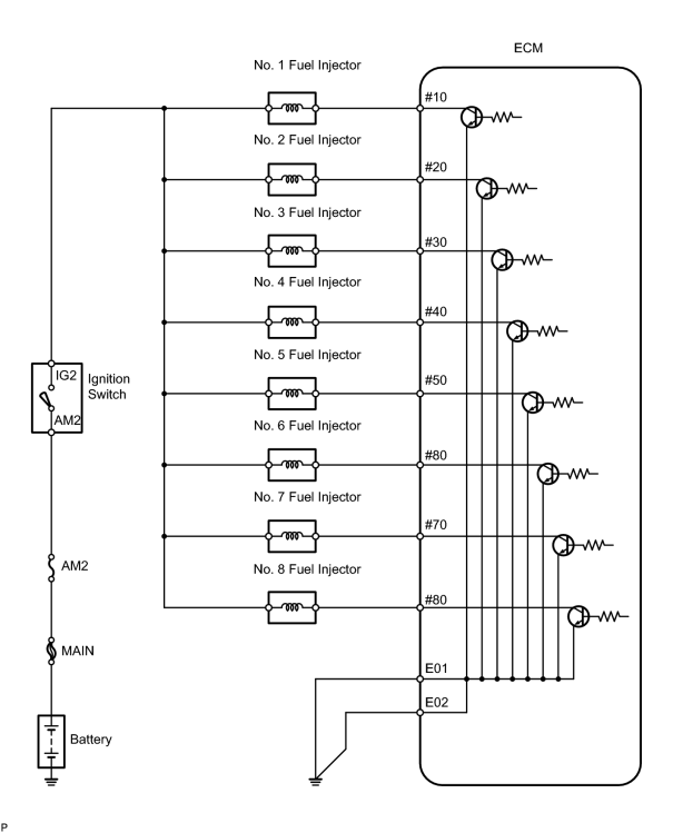
WIRING DIAGRAM
CONFIRMATION DRIVING PATTERN
- Connect the intelligent tester to the CAN VIM. Then connect the CAN VIM to the DLC3.
- Record the DTC and freeze frame data.
-
Set check mode on the intelligent tester
.
- Read the value on the misfire counter for each cylinder when idling. If the value is displayed on the misfire counter, skip the following procedure of confirmation driving.
-
Drive the vehicle several times while using the DATA LIST's MISFIRE RPM and MISFIRE LOAD menu items to keep track of the vehicle's engine speed, load and its surrounding range.
If you have no intelligent tester, turn the ignition switch OFF after the symptom is simulated once. Then repeat the simulation process.
HINT:
In order to force output of the DTC, it is necessary to drive with MISFIRE RPM and MISFIRE LOAD selected in the DATA LIST for the period of time in the chart below. Do not turn the ignition switch OFF. Turning the ignition switch OFF switches the diagnosis system from check mode to normal mode and all DTCs, freeze frame data and other data are erased.
Engine RPM
Time
Idling
3.5 minutes or more
1,000 rpm
3 minutes or more
2,000 rpm
1.5 minutes or more
3,000 rpm
1 minute or more
- Check if a misfire occurs by monitoring DTC output and the freeze frame data. Then, record the DTCs, freeze frame data and misfire counter data.
- Turn the ignition switch OFF and wait for at least 5 seconds.
INSPECTION PROCEDURE
HINT:
- If DTCs other than misfire DTCs are output simultaneously, troubleshoot the non-misfire DTCs first.
- Read freeze frame data using the intelligent tester. Freeze frame data records the engine conditions when malfunctions are detected. When troubleshooting, freeze frame data can help determine if the vehicle was running or stopped, if the engine was warmed up or not, if the air fuel ratio was lean or rich, and other data from the time the malfunction occurred.
- If the misfire does not occur when the vehicle is brought to the workshop, the misfire can be confirmed by reproducing the conditions recorded in the freeze frame data. Also, after finishing repairs, confirm that no misfire occurs (see confirmation driving pattern).
-
On 6 and 8 cylinder engines, cylinder-specific misfire fault codes are disabled at high engine speeds.
If the misfire starts in a high engine speed range or the misfire occurs only in a high engine speed area, only general fault code P0300 will be stored.
When only P0300 is stored:
- Erase the general misfire fault code from the intelligent tester.
- Start the engine and drive the confirmation pattern (see confirmation driving pattern).
- Read the value of the misfire ratio for each cylinder. Or, check if a DTC was output.
- Perform repairs on the cylinder that has a high misfire ratio. Or repair the cylinder indicated by any output DTCs.
- After finishing repairs, drive the confirmation pattern again and confirm that no misfire occurs.
- If either SHORT FT #1, LONG FT #1, SHORT FT #2 or LONG FT #2 in the freeze frame data is +-20%, there is a possibility that the air fuel ratio is becoming RICH (-20% or less) or LEAN (+20% or more).
- When COOLANT TEMP in the freeze frame data is less than 75°C (167°F), a misfire is only possible during engine warm-up.
- If the misfire cannot be reproduced, the cause may be: 1) low fuel in the vehicle, 2) improper fuel in the vehicle, 3) a contaminated ignition plug, or 4) another problem.
- Be sure to check the value on the misfire counter after repairs.
PROCEDURE
|
1. |
CHECK OTHER DTC OUTPUT (IN ADDITION TO MISFIRE DTCS) |
(a) Connect the intelligent tester to the CAN VIM. Then connect the CAN VIM to the DLC3.
(b) Turn the ignition switch ON and turn the intelligent tester ON.
(c) Enter the following menus: DIAGNOSIS / ENHANCED OBD II / DTC INFO / CURRENT CODES.
(d) Read the CURRENT CODES.
|
Display (DTC output) |
Proceed to |
|---|---|
|
P0300, P0301, P0302, P0303, P0304, P0305, P0306, P0307 or P0308 |
A |
|
P0300, P0301, P0302, P0303, P0304, P0305, P0306, P0307 or P0308 and other DTCs |
B |
HINT:
If any DTCs other than P0300, P0301, P0302, P0303, P0304, P0305, P0306, P0307 and P0308 are output, troubleshoot those DTCs first.
| B |

|
|

|
2. |
READ VALUE USING INTELLIGENT TESTER (MISFIRE RPM AND MISFIRE LOAD) |
(a) Connect the intelligent tester to the CAN VIM. Then connect the CAN VIM to the DLC3.
(b) Turn the ignition switch ON and turn the intelligent tester ON.
(c) Enter the following menus: DIAGNOSIS / ENHANCED OBD II / DATA LIST / MISFIRE / MISFIRE RPM and MISFIRE LOAD.
(d) Read and note the MISFIRE RPM and the MISFIRE LOAD (engine load) with the DATA LIST.
HINT:
The MISFIRE RPM and MISFIRE LOAD displays have vehicle data that can help lead to successful repairs of any misfiring cylinders.
|
|
3. |
CHECK CONNECTION OF VENTILATION HOSE |
OK:
Ventilation hose is connected correctly and is not damaged.
| NG |
|
|
|
4. |
CHECK MISFIRE COUNT (CYL #1, #2, #3, #4, #5, #6, #7, #8) |
(a) Connect the intelligent tester to the CAN VIM. Then connect the CAN VIM to the DLC3.
(b) Turn the ignition switch ON and turn the intelligent tester ON.
(c) Clear the DTCs.
(d) Enter the following menus: DIAGNOSIS / ENHANCED OBD II / DATA LIST / MISFIRE.
(e) Allow the engine to idle.
(f) Read the misfire count of the cylinders #1 to #8.
If no misfire is counted for all of the cylinders, move the shift lever into the D position and repeat the 2 previous steps.
If misfires are still not counted, perform the next 2 steps.
(g) Drive the vehicle with MISFIRE RPM and MISFIRE LOAD selected in the DATA LIST.
(h) Read the misfire count of cylinders #1 to #8, or check for any output DTCs.
|
Misfire count in each cylinder |
Proceed to |
|---|---|
|
1 or 2 cylinders have some misfire counts |
A |
|
3 cylinders or more have some misfire counts |
B |
HINT:
- If it is difficult to reproduce misfires for each cylinder, check the DATA LIST item called MISFIRE MARGIN. Try to find vehicle driving conditions that lower the MISFIRE MARGIN value. Values above 30% are considered normal.
- If the freeze frame data's record of the ECT is below 75°C (167°F), the misfire may be detected only when the engine is cold.
- If the freeze frame data's record of the ENGINE RUN TIME is below 120 seconds, the misfire may be detected right after the engine is started.
| B |
|
|
|
5. |
PERFORM ACTIVE TEST USING INTELLIGENT TESTER (FUEL CUT #1 TO #8) |
(a) Connect the intelligent tester to the CAN VIM. Then connect the CAN VIM to the DLC3.
(b) Turn the ignition switch ON and turn the intelligent tester ON.
(c) Allow the engine to idle.
(d) Enter the following menus: DIAGNOSIS / ENHANCED OBD II / ACTIVE TEST / FUEL CUT #1 (to #8).
(e) If a cylinder has a high misfire count, cut fuel to the cylinder. Compare the misfire count of the cylinder before fuel cut and after fuel cut.
|
Misfire count in each cylinder |
Proceed to |
|---|---|
|
Misfire count of the cylinder before fuel cut and after fuel cut are roughly the same |
A |
|
Misfire count of the cylinder before fuel cut is lower than after fuel cut |
B |
HINT:
If the misfire count of the cylinder before fuel cut and after fuel cut are roughly the same, the cylinder is misfiring.
If the misfire count of the cylinder before fuel cut is lower than after fuel cut, the cylinder misfires sometimes.
NOTICE:
This ACTIVE TEST cannot be performed while the vehicle is being driven.
| B |
|
|
|
6. |
INSPECT SPARK PLUG |
|
(a)
Remove the engine cover
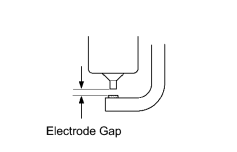
(b) Remove the ignition coil and the spark plug of misfire cylinder. (c) Measure the spark plug electrode gap. Standard: The electrode gap is 1.0 to 1.3 mm (0.039 to 0.051 in.) (d) Check the electrode for carbon deposits. Recommended spark plug:
NOTICE: If the electrode gap is larger than the standard, replace the spark plug. Do not adjust the electrode gap. |
|
| NG |
|
|
|
7. |
CHECK SPARK AND IGNITION |
|
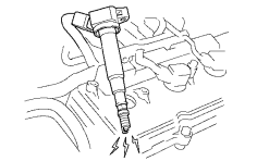
(a) Disconnect the fuel injector connectors to prevent the engine from starting. (b) Install the spark plug to the ignition coil. (c) Attach the spark plug to the cylinder head cover. (d) Crank the engine for 2 seconds or less and check if a spark occurs. OK: Spark occurs |
|
| NG |
|
|
|
8. |
CHECK CYLINDER COMPRESSION PRESSURE ON MISFIRING CYLINDER |
(a) Measure the cylinder compression pressure of the misfiring cylinder.
| OK |
|
| NG |
|
|
9. |
CHANGE NORMAL SPARK PLUG AND CHECK SPARK OF MISFIRING CYLINDER |
(a) For inspection purposes, remove the current spark plug and install a normally functioning spark plug.
(b) Perform a spark test.
CAUTION:
Always disconnect each injector connector.
NOTICE:
Do not crank the engine for more than 2 seconds.
(1) Install the spark plug to the ignition coil and connect the ignition coil connector.
(2) Disconnect the injector connector.
(3) Ground the spark plug.
(4) Check if a spark occurs while the engine is being cranked.
OK:
Spark jumps across electrode gap.
| OK |
|
| NG |
|
REPLACE IGNITION COIL (THEN CONFIRM THAT THERE IS NO MISFIRE) |
|
10. |
CHECK ECM (#10, #20, #30, #40, #50, #60, #70, #80 VOLTAGE) |
|
(a) Turn the ignition switch ON. (b) Measure the voltage of the ECM connectors. Standard voltage:
|
|
| OK |
|
|
|
11. |
CHECK HARNESS AND CONNECTOR (FUEL INJECTOR - ECM) |
(a)
Check harness and connector
.
| NG |
|
|
|
12. |
CHECK FUEL INJECTOR OF MISFIRING CYLINDER |
Check the injector injection (whether fuel volume is high or low, and whether injection pattern is poor).
| NG |
|
|
|
13. |
CHECK VALVE CLEARANCE OF MISFIRING CYLINDER |
| NG |
|
|
|
14. |
CHECK AIR INDUCTION SYSTEM |
(a) Check the air induction system for vacuum leakage.
OK:
No leakage from air induction system
| NG |
|
|
|
15. |
CHECK VALVE TIMING |
|
(a)
Remove the engine cover
(b)
Remove the drive belt
(c)
Remove the timing belt cover LH and RH
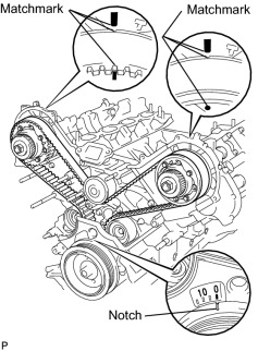
(d) Turn the crankshaft to align the matchmarks of the crankshaft. (e) Align the notch of the crankshaft pulley with the "0" position. (f) Confirm whether the matchmarks of the camshaft pulley and cylinder head cover are facing each other. (g) If the matchmarks are not facing each other, turn the crankshaft clockwise by 360°. Confirm again if the matchmarks are facing each other. OK: The matchmarks of the camshaft pulley and the cylinder head cover face each other when the notch of the crankshaft pulley is in the "0" position. |
|
| NG |
|
|
|
16. |
CHECK FUEL PRESSURE |
Check the fuel pressure
.
| NG |
|
CHECK AND REPLACE FUEL PUMP, FUEL PRESSURE REGULATOR, FUEL PIPE LINE AND FILTER |
|
|
17. |
READ VALUE USING INTELLIGENT TESTER (COOLANT TEMP) |
(a) Connect the intelligent tester to the CAN VIM. Then connect the CAN VIM to the DLC3.
(b) Turn the ignition switch ON and turn the intelligent tester ON.
(c) Enter the following menus: DIAGNOSIS / ENHANCED OBD II / DATA LIST / PRIMARY / COOLANT TEMP.
(d) Read the COOLANT TEMP value when the engine is cold and warmed-up.
Standard:
ECT when the engine is cold: Same as ambient temperature
ECT when the engine is warmed-up: 75 to 95°C (167 to 203°F)
| NG |
|
|
|
18. |
READ VALUE USING INTELLIGENT TESTER (MAF) |
(a) Connect the intelligent tester to the CAN VIM. Then connect the CAN VIM to the DLC3.
(b) Turn the ignition switch ON and turn the intelligent tester ON.
(c) Enter the following menus: DIAGNOSIS / ENHANCED OBD II / DATA LIST / PRIMARY / MAF and COOLANT TEMP.
(d) Allow the engine to idle until the COOLANT TEMP reaches 75°C (167°F) or more.
(e) Read the MAF with the engine in an idling condition and at an engine speed of 2,500 rpm.
Standard:
MAF at idle rpm: 4.0 to 8.0 g/s (shift lever is in N position and A/C is OFF)
MAF at 2,500 rpm: 10.0 to 20.0 g/s (shift lever is in N position and A/C is OFF)
| NG |
|
| OK |
|

|

|