- Open or short in camshaft position sensor circuit
- Camshaft position sensor
- Camshaft timing pulley LH
- ECM
| Last Modified: 4-30-2014 | 6.6 C | Doc ID: RM000000TMH007X |
| Model Year: 2006 | Model: LX470 | Prod Date Range: [05/2005 - ] |
| Title: 2UZ-FE ENGINE CONTROL SYSTEM: SFI SYSTEM: P1340,P1341; Camshaft Position Sensor "A" (Bank 1 Sensor 2); 2006 MY LX470 [05/2005 - ] | ||
|
DTC |
P1340 |
Camshaft Position Sensor "A" (Bank 1 Sensor 2) |
|
DTC |
P1341 |
Camshaft Position Sensor "A" (Bank 1 Sensor 2 ) |
DESCRIPTION
The camshaft position sensor (G signal) consists of a magnet, iron core and pickup coil.
The camshaft drive gear (LH) has 3 teeth on its inner circumstance. When the camshaft gear rotates, air gap changes between the protrusion on the gear and the pickup coil. The change affects the magnetic field and results in changes in the resistance of the MRE element.
The crankshaft signal plate has 34 teeth and is mounted on the crankshaft. The crankshaft position sensor generates 34 signals at every engine revolution. The ECM detects the standard crankshaft angle based on the G signal and the actual crankshaft angle and the engine speed by the NE signal.
|
DTC No. |
DTC Detection Condition |
Trouble Area |
|---|---|---|
|
P1340 P1341 |
No camshaft position sensor signal to ECM during cranking (2 trip detection logic) |
|
|
No camshaft position sensor signal to ECM with engine speed 600 rpm or more |
MONITOR DESCRIPTION
The camshaft position sensor (G signal) consists of a magnet and MRE element.
The camshaft drive gear has 3 teeth on its inner circumference. When the camshaft gear rotates, air gap changes between the protrusion on the gear and the pickup coil. The change affects the magnetic filed and results in changes in the resistance of the MRE element. The crankshaft angle sensor plate has 34 teeth and outputs 34 signals at every engine revolution. The ECM detects the standard crankshaft angle based on the G signal and actual crankshaft angle and engine speed by NE signal.
MONITOR STRATEGY
|
Related DTCs |
P1340: Camshaft position sensor range check P1340: Camshaft position / Crankshaft position misalignment P1341: Camshaft position sensor malfunction |
|
Required Sensors/Components (Main) |
Camshaft position sensor |
|
Required Sensors/Components (Related) |
Crankshaft position sensor, Engine speed sensor |
|
Frequency of Operation |
Continuous |
|
Duration |
5 seconds |
|
MIL Operation |
2 driving cycles: Camshaft position sensor range check Immediate: Camshaft position / Crankshaft position misalignment and camshaft position sensor malfunction |
|
Sequence of Operation |
None |
TYPICAL ENABLING CONDITIONS
|
The monitor will run whenever these DTCs are not present |
- |
Camshaft position sensor range check:
|
Starter |
ON |
|
Minimal battery voltage while starter ON |
Less than 11 V |
Camshaft position / Crankshaft position misalignment:
|
Engine RPM |
600 rpm or more |
|
Starter |
OFF |
Camshaft position sensor malfunction:
|
Starter |
After OFF to ON timing |
TYPICAL MALFUNCTION THRESHOLDS
Camshaft position sensor range check:
|
Camshaft position signal |
No signal |
Camshaft position / Crankshaft position misalignment:
|
Camshaft position and crankshaft position phase |
Misaligned |
Camshaft position sensor malfunction:
|
Camshaft position and crankshaft position phase |
Misaligned |
|
Camshaft position signal per 2 revolutions of crankshaft |
12 signals or more |
COMPONENT OPERATING RANGE
|
Camshaft position sensor signal |
|
WIRING DIAGRAM
Refer to DTC P0335
![2006 MY LX470 [05/2005 - ]; 2UZ-FE ENGINE CONTROL SYSTEM: SFI SYSTEM: P0335,P0339; Crankshaft Position Sensor "A" Circuit+](../../../../stylegraphics/info.gif "2006 MY LX470 [05/2005 - ]; 2UZ-FE ENGINE CONTROL SYSTEM: SFI SYSTEM: P0335,P0339; Crankshaft Position Sensor \"A\" Circuit+") .
.
INSPECTION PROCEDURE
HINT:
Read freeze frame data using the intelligent tester. Freeze frame data records the engine conditions when malfunctions are detected. When troubleshooting, freeze frame data can help determine if the vehicle was running or stopped, if the engine was warmed up or not, if the air fuel ratio was lean or rich, and other data from the time the malfunction occurred.
PROCEDURE
|
1. |
CHECK HARNESS AND CONNECTOR (SENSOR POWER SOURCE) |
|
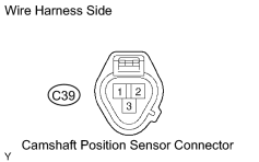
(a) Disconnect the C39 camshaft position sensor connector. (b) Turn the ignition switch ON. (c) Measure the voltage between terminal 3 of the camshaft position sensor connector and body ground. Standard voltage:
(d) Reconnect the camshaft position sensor connector. |
|
| NG |

|
|

|
2. |
CHECK ECM TERMINAL VOLTAGE |
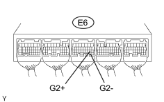
(a) Inspect the ECM using an oscilloscope.
|
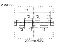
(1) While the engine is idling, check the waveform between the terminals of the ECM connector. Standard voltage:
HINT:
|
|
| OK |
|
|
|
3. |
CHECK HARNESS AND CONNECTOR (ECM - CAMSHAFT POSITION SENSOR) |
(a)
Check harness and connector
.
| NG |
|
|
|
4. |
INSPECT SENSOR INSTALLATION |
|
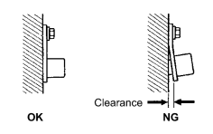
(a) Check the camshaft position sensor installation. OK: The camshaft position sensor is installed properly. |
|
| NG |
|
|
|
5. |
INSPECT CAMSHAFT TIMING PULLEY LH (SIGNAL PLATE TOOTH) |
| NG |
|
| OK |
|

|

|