| Last Modified: 4-30-2014 | 6.6 J | Doc ID: RM000000TMT00AX |
| Model Year: 2006 | Model: LX470 | Prod Date Range: [05/2005 - ] |
| Title: 2UZ-FE ENGINE CONTROL SYSTEM: SFI SYSTEM: MIL Circuit; 2006 MY LX470 [05/2005 - ] | ||
|
MIL Circuit |
DESCRIPTION
The Malfunction Indicator Lamp (MIL) is used to indicate the ECM's detection of a vehicle malfunction.
The instrument panel MET fuse provides the circuit with power and the ECM provides the circuit ground that illuminates the MIL.
MIL operations should be checked visually:
The MIL should be illuminated when the ignition switch is turned ON. If the MIL is always ON or OFF, use the intelligent tester and follow the procedures below to determine the cause of the problem.
If the ECM detects trouble, the MIL illuminates. At this time, the ECM records a DTC in the memory.
WIRING DIAGRAM
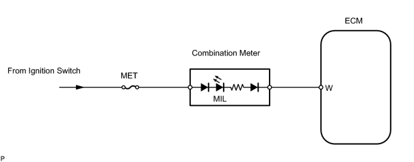
INSPECTION PROCEDURE
PROCEDURE
|
1. |
CHECK THAT MILL IS ILLUMINATED |
(a) Perform troubleshooting in accordance with the chart below.
|
Condition |
Proceed to |
|---|---|
|
MIL remains ON |
A |
|
MIL does not illuminate |
B |
| B |

|
|

|
2. |
CHECK WHETHER MIL TURNS OFF |
(a) Connect the intelligent tester to the CAN VIM. Then connect the CAN VIM to the DLC3.
(b) Turn the ignition switch ON and turn the intelligent tester ON.
(c)
Check whether any DTCs have been stored
![2006 MY LX470 [05/2005 - 01/2006]; 2UZ-FE ENGINE CONTROL SYSTEM: SFI SYSTEM: DIAGNOSTIC TROUBLE CODE CHART](../../../../stylegraphics/info.gif "2006 MY LX470 [05/2005 - 01/2006]; 2UZ-FE ENGINE CONTROL SYSTEM: SFI SYSTEM: DIAGNOSTIC TROUBLE CODE CHART") . Note them down if necessary.
. Note them down if necessary.
(d)
Clear the DTC
.
(e) Check if the MIL turns off.
OK:
MIL should turn off.
| OK |
|
|
|
3. |
CHECK HARNESS AND CONNECTOR (CHECK FOR SHORT IN WIRE HARNESS) |
|
(a) Disconnect the E9 ECM connector. (b) Turn the ignition switch ON. (c) Check that the MIL is not illuminated. OK: MIL is not illuminated. |
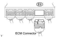
|
| OK |
|
|
|
4. |
CHECK HARNESS AND CONNECTOR (COMBINATION METER - ECM) |
(a)
Check harness and connector
.
| OK |
|
| NG |
|
|
5. |
CHECK THAT MIL IS ILLUMINATED |
(a) Check that the MIL is illuminated when turning the ignition switch ON.
OK:
MIL is illuminated.
| OK |
|
|
|
6. |
CHECK THAT ENGINE STARTS |
(a) Turn the ignition switch ON.
(b) Start the engine.
|
Result |
Proceed to |
|---|---|
|
Engine starts |
A |
|
Engine does not start* |
B |
HINT:
*: The intelligent tester cannot communicate with the ECM.
| B |
|
|
|
7. |
INSPECT COMBINATION METER (MIL CIRCUIT) |
(a)
See the combination meter troubleshooting section
.
| NG |
|
| OK |
|
CHECK AND REPLACE HARNESS OR CONNECTOR (COMBINATION METER - ECM) |

|

|