-
Advanced cam timing:
After engine is warmed up and engine speed is at 400 to 4,000 rpm, condition (a) or (b) continues (1 trip detection logic):
- (a) Valve timing does not change from current valve timing
- (b) Current valve timing is fixed (difference between "target" and "actual" camshaft timing is more than 5° CA for 4.5 seconds and camshaft timing change is less than 5° CA for 5 seconds)
| Last Modified: 4-30-2014 | 6.6 C | Doc ID: RM000000TSG00BX |
| Model Year: 2006 | Model: LX470 | Prod Date Range: [05/2005 - ] |
| Title: 2UZ-FE ENGINE CONTROL SYSTEM: SFI SYSTEM: P0011,P0012,P0021,P0022; Camshaft Position "A" - Timing Over-Advanced or System Performance (Bank 1); 2006 MY LX470 [05/2005 - ] | ||
|
DTC |
P0011 |
Camshaft Position "A" - Timing Over-Advanced or System Performance (Bank 1) |
|
DTC |
P0012 |
Camshaft Position "A" - Timing Over-Retarded (Bank 1) |
|
DTC |
P0021 |
Camshaft Position "A" - Timing Over-Advanced or System Performance (Bank 2) |
|
DTC |
P0022 |
Camshaft Position "A" - Timing Over-Retarded (Bank 2) |
DESCRIPTION
HINT:
- Refer to DTC P0011, P0012, P0021 and P0022 is present, check the Variable Valve Timing (VVT) system.
-
Refer to DTC P0010
![2006 MY LX470 [05/2005 - ]; 2UZ-FE ENGINE CONTROL SYSTEM: SFI SYSTEM: P0010,P0020; Camshaft Position "A" Actuator Circuit (Bank 1)+](../../../../stylegraphics/info.gif "2006 MY LX470 [05/2005 - ]; 2UZ-FE ENGINE CONTROL SYSTEM: SFI SYSTEM: P0010,P0020; Camshaft Position \"A\" Actuator Circuit (Bank 1)+") .
.
|
DTC No. |
DTC Detection Condition |
Trouble Area |
|---|---|---|
|
P0011 P0021 |
|
|
|
P0012 P0022 |
|
|
MONITOR DESCRIPTION
The ECM optimizes the valve timing using the Variable Valve Timing (VVT) system to control the intake valve camshaft. The VVT system includes the ECM, the OCV and the VVT actuator. The ECM sends a target "duty-cycle" control signal to the OCV. This control signal, applied to the OCV, regulates the oil pressure supplied to the VVT controller. The VVT controller can advance or retard the intake valve camshaft.
Example:
A DTC will set if: 1) the difference between the target and actual valve timing is more than 5° of the Crankshaft Angle (CA) and the condition continues for more than 4.5 seconds; or 2) the OCV is forcibly activated 63 times or more.
Advanced cam DTCs are subject to 1 trip detection logic.
Retarded cam DTCs are subject to 2 trip detection logic.
The monitor runs if all the conditions below are met:
- After engine warm-up (engine coolant temperature is 75°C (167°F) or more).
- After driving the vehicle over 40 km/h (25 mph) for 3 minutes.
- After idling the engine for 3 minutes.
MONITOR STRATEGY
|
Related DTCs |
P0011: Advance camshaft timing (bank 1) P0012: Retard camshaft timing (bank 1) P0021: Advance camshaft timing (bank 2) P0022: Retard camshaft timing (bank 2) |
|
Required Sensors/Components (Main) |
OCV and VVT actuator |
|
Required Sensors/Components (Related) |
Engine Coolant Temperature sensor, Camshaft position sensor, Crankshaft position sensor |
|
Frequency of Operation |
Once per driving cycle |
|
Duration |
10 seconds |
|
MIL Operation |
P0011 and P0021: Immediate P0012 and P0022: 2 driving cycles |
|
Sequence of Operation |
None |
TYPICAL ENABLING CONDITIONS
|
Monitor will run whenever these DTCs are not present |
P0100 - P0103 (MAF sensor) P0115 - P0118 (ECT sensor) P0125 (Insufficient ECT for closed loop) P0335 (CKP sensor) P0340, P0341 (CMP sensor) P0351 - P0358 (igniter) |
|
Battery voltage |
11 V or more |
|
Engine RPM |
400 to 4,000 rpm |
|
ECT |
75 to 100°C (167 to 212°F) |
TYPICAL MALFUNCTION THRESHOLDS
Advance:
|
Both of the following conditions are met |
- |
|
(a) Deviation of valve timing |
More than 5° CA (crankshaft angle) |
|
(b) Valve timing |
No change at advanced valve timing |
Retarded:
|
Both of the following conditions are met |
- |
|
(a) Deviation of valve timing |
More than 5° CA (crankshaft angle) |
|
(b) Valve timing |
No change at retarded valve timing |
If the difference between target and actual camshaft timing is larger than the specified value, the ECM operates the VVT actuator.
Then, the ECM monitors the camshaft timing change for 5 seconds.
WIRING DIAGRAM
Refer to DTC P0010
.
INSPECTION PROCEDURE
|
Abnormal bank |
Advanced timing over (Valve timing is out of specified range) |
Retarded timing over (Valve timing is out of specified range) |
|
Bank 1 |
P0011 |
P0012 |
|
Bank 2 |
P0021 |
P0022 |
- If DTC P0011 or P0012 is displayed, check the bank 1 Variable Valve Timing (VVT) system circuit.
- If DTC P0021 or P0022 is displayed, check the bank 2 VVT system circuit.
- Bank 1 includes No. 1 cylinder, but bank 2 does not. No. 1 cylinder is located in the front part of the engine, opposite the transmission.
- Read freeze frame data using the intelligent tester. Freeze frame data records the engine conditions when malfunctions are detected. When troubleshooting, freeze frame data can help determine if the vehicle was running or stopped, if the engine was warmed up or not, if the air fuel ratio was lean or rich, and other data from the time the malfunction occurred.
NOTICE:
DTC P0011, P0012, P0021 or P0022 is also output when a foreign object is detected in some parts of the system in the engine oil, and then the system returns to normal in a short time. As the ECM is controlled to eject a foreign object, there is no problem with the VVT. There is also no problem with the VVT as the oil filter should catch the foreign object in the engine oil.
PROCEDURE
|
1. |
PERFORM ACTIVE TEST USING INTELLIGENT TESTER (OCV OPERATION) |
(a) Connect the intelligent tester to the CAN VIM. Then connect the CAN VIM to the DLC3.
(b) Start the engine and warm it up.
(c) Enter the following menus: DIAGNOSIS / ENHANCED OBD II / ACTIVE TEST / VVT CTRL B1 or VVT CTRL B2.
(d) Using the intelligent tester, operate the Oil Control Valve (OCV) and check the engine speed.
Standard:
|
Tester Operation |
Specified Condition |
|---|---|
|
OCV is OFF |
Normal engine speed |
|
OCV is ON |
Rough idle or engine stall |
| NG |

|
|

|
2. |
PERFORM ACTIVE TEST USING INTELLIGENT TESTER (OCV OPERATION) |
(a) Enter the following menus: DIAGNOSIS / ENHANCED OBD II / ACTIVE TEST / VVT B1 or VVT B2.
(b) Change the VVT B1 and VVT B2 values to a value between -100% to 100%.
HINT:
VVT B1 and VVT B2 values should be added to the current OCV duty ratio.
(c) Confirm the current VVT angle by checking VVTL CHNG ANGL #1 and VVTL CHNG ANGL #2.
OK:
Operation of VVT B1 or VVT B2 leads to an immediate, linear change in the VVT angle.
NOTICE:
- With the engine idling and with the advanced camshaft timing (VVT B1 or VVT B2 has a value of 0% to 100%), engine revolutions will be rough or the engine will stall.
- When the vehicle is being driven, if the engine is turned off or the throttle valve is open, this ACTIVE TEST will automatically be canceled.
| NG |
|
|
|
3. |
CHECK IF DTC OUTPUT REOCCUR (DTC P0011, P0012, P0021 OR P0022) |
(a)
Select check mode
.
(b) Start and warm up the engine.
(c) Drive the vehicle for 10 minutes or more.
(d) Read the DTC.
OK:
No DTC is output.
| OK |
|
|
|
4. |
CHECK VALVE TIMING (CHECK FOR LOOSE AND JUMPED TOOTH OF TIMING BELT) |
|
(a)
Remove the engine cover
(b)
Remove the drive belt
(c)
Remove the timing belt cover LH and RH
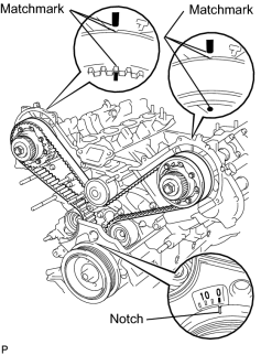
(d) Turn the crankshaft to align the matchmarks of the crankshaft. (e) Align the notch of the crankshaft pulley with the "0" position. (f) Confirm whether the matchmarks of the camshaft pulley and cylinder head cover are facing each other. (g) If the matchmarks are not facing each other, turn the crankshaft clockwise by 360°. Confirm again if the matchmarks are facing each other. OK: The matchmarks of the camshaft pulley and the cylinder head cover face each other when the notch of the crankshaft pulley is in the "0" position. |
|
| NG |
|
|
|
5. |
INSPECT CAMSHAFT TIMING OIL CONTROL VALVE ASSEMBLY |
|
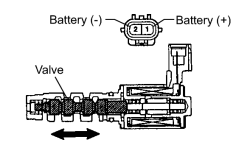
(a) Disconnect the C40 or C41 Oil Control Valve (OCV) connector. (b) Measure the resistance of the OCV. Standard resistance: 6.9 to 7.9 Ω at 20°C (68°F) (c) Remove the OCV. (d) Apply battery voltage to the terminals of the OCV. (e) Check the valve operation. OK: The valve moves quickly. |
|
| NG |
|
|
|
6. |
INSPECT OIL CONTROL VALVE FILTER |
|
(a)
Remove the cylinder head cover
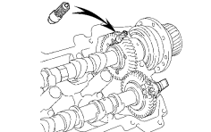
(b) Remove the camshaft bearing cap and OCV filter. (c) Check that the filter is not clogged. OK: The filter is not clogged. |
|
| NG |
|
|
|
7. |
REPLACE CAMSHAFT TIMING TUBE ASSEMBLY |
(a) After replacing camshaft timing tube assembly, confirm that the DTC output does not recur.
(b) Connect the intelligent tester to the CAN VIM. Then connect the CAN VIM to the DLC3.
(c) Turn the ignition switch ON and turn the tester ON.
(d)
Clear the DTCs
.
(e) Start and warm up the engine.
(f)
Switch the ECM from normal mode to check mode using the tester
.
(g) Drive the vehicle for 10 minutes or more.
(h) Confirm that no DTC is set using the tester.
| NEXT |
|

|

|