- Open or short in Intake Air Temperature (IAT) sensor circuit
- Intake Air Temperature (IAT) sensor (built into Mass Air Flow [MAF] meter)
- ECM
| Last Modified: 4-30-2014 | 6.6 C | Doc ID: RM000000UBX00CX |
| Model Year: 2006 | Model: LX470 | Prod Date Range: [05/2005 - ] |
| Title: 2UZ-FE ENGINE CONTROL SYSTEM: SFI SYSTEM: P0110,P0112,P0113; Intake Air Temperature Circuit; 2006 MY LX470 [05/2005 - ] | ||
|
DTC |
P0110 |
Intake Air Temperature Circuit |
|
DTC |
P0112 |
Intake Air Temperature Circuit Low Input |
|
DTC |
P0113 |
Intake Air Temperature Circuit High Input |
DESCRIPTION
-
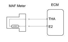
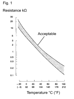 The Intake Air Temperature (IAT) sensor, built into the Mass Air Flow (MAF) meter, monitors the intake air temperature. The IAT sensor has a thermistor that varies its resistance depending on the intake air temperature. When the intake air temperature is low, the resistance in the thermistor increases. When the temperature is high, the resistance drops. The variations in resistance are reflected as voltage changes to the ECM terminal (see Fig. 1).
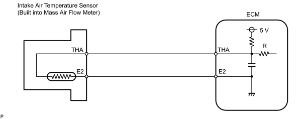
The IAT sensor is connected to the ECM. The 5 V power source voltage in the ECM is applied to the IAT sensor from terminal THA via resistor R.
The resistor R and the IAT sensor are connected in series. When the resistance value of the IAT sensor changes in accordance with changes in the intake air temperature, the voltage at terminal THA also changes. Based on this signal, the ECM increases the fuel injection volume to improve driveability during cold engine operation.
|
DTC No. |
DTC Detection Condition |
Trouble Area |
|---|---|---|
|
P0110 |
Open or short in IAT sensor circuit for 0.5 seconds (1 trip detection logic) |
|
|
P0112 |
Short in IAT sensor circuit for 0.5 seconds (1 trip detection logic) |
|
|
P0113 |
Open in IAT sensor circuit for 0.5 seconds (1 trip detection logic) |
|
HINT:
After confirming DTC "P0110, P0112 or P0113", use the intelligent tester to confirm the intake air temperature in the "DIAGNOSIS / ENHANCED OBD II / PRIMARY / INTAKE AIR".
|
Temperature Displayed |
Malfunction |
|---|---|
|
-40°C (-40°F) |
Open circuit |
|
140°C (284°F) or more |
Short circuit |
MONITOR DESCRIPTION
The ECM monitors the sensor voltage and uses this value to calculate the intake air temperature. When the sensor output voltage deviates from the normal operating range, the ECM interprets this as a fault in the IAT sensor and sets a DTC.
Example:
When the sensor voltage output is -40°C (-40°F) or more than 140°C (284°F) and if either condition continues for 0.5 seconds or more, the ECM will set a DTC.
This monitor runs 0.5 seconds after the ignition switch is turned ON.
MONITOR STRATEGY
|
Related DTCs |
P0110: IAT sensor range check (fluttering) P0112: IAT sensor range check (low resistance) P0113: IAT sensor range check (high resistance) |
|
Required Sensors/Components (Main) |
IAT sensor |
|
Required Sensors/Components (Related) |
- |
|
Frequency of Operation |
Continuous |
|
Duration |
0.5 seconds |
|
MIL Operation |
Immediate |
|
Sequence of Operation |
None |
TYPICAL ENABLING CONDITIONS
|
Monitor will run whenever these DTCs are not present |
None |
|
The typical enabling condition is not available |
- |
TYPICAL MALFUNCTION THRESHOLDS
P0110:
|
IAT sensor voltage [Intake air temperature] |
Less than 0.18 V, or more than 4.91 V |
P0112:
|
IAT sensor voltage [Intake air temperature] |
Less than 0.18 V |
P0113:
|
IAT sensor voltage [Intake air temperature] |
More than 4.91 V |
COMPONENT OPERATING RANGE
|
IAT sensor resistance [IAT] |
98.5 Ω to 156 kΩ [-40 to 140°C (-40 to 284°F)] |
WIRING DIAGRAM
INSPECTION PROCEDURE
HINT:
- If other DTCs relating to different systems that have terminal E2 as the ground terminal are output simultaneously, terminal E2 may have an open circuit.
- Read freeze frame data using the intelligent tester. Freeze frame data records the engine conditions when a malfunction is detected. When troubleshooting, freeze frame data can help determine if the vehicle was running or stopped, if the engine was warmed up or not, if the air fuel ratio was lean or rich, and other data from the time the malfunction occurred.
PROCEDURE
|
1. |
READ VALUE USING INTELLIGENT TESTER (INTAKE AIR TEMPERATURE) |
(a) Connect the intelligent tester to the CAN VIM. Then connect the CAN VIM to the DLC3.
(b) Turn the ignition switch ON and turn the intelligent tester ON.
(c) Enter the following menus: DIAGNOSIS / ENHANCED OBD II / DATA LIST / PRIMARY / INTAKE AIR.
(d) Read the values.
Standard:
Same as actual Intake Air Temperature (IAT).
|
Intake Air Temperature |
Proceed to |
|---|---|
|
-40°C (-40°F) |
A |
|
140°C (284°F) or more |
B |
|
OK (same as present temperature) |
C |
HINT:
If there is an open circuit, the intelligent tester indicates -40°C (-40°F).
If there is a short circuit, the intelligent tester indicates 140°C (284°F) or more.
| B |

|
| C |
|
|

|
2. |
READ VALUE USING INTELLIGENT TESTER (CHECK FOR OPEN IN WIRE HARNESS) |
|
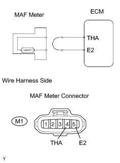
(a) Disconnect the M1 Mass Air Flow (MAF) meter connector. (b) Connect terminals THA of the MAF meter wire harness side connector. (c) Connect the intelligent tester to the CAN VIM. Then connect the CAN VIM to the DLC3. (d) Turn the ignition switch ON and turn the intelligent tester ON. (e) Enter the following menus: DIAGNOSIS / ENHANCED OBD II / DATA LIST / PRIMARY / INTAKE AIR. (f) Read the value. Standard: 140°C (284°F) or more |
|
| OK |
|
CONFIRM GOOD CONNECTION TO SENSOR. IF OK, REPLACE MASS AIR FLOW METER |
|
|
3. |
READ VALUE USING INTELLIGENT TESTER (CHECK FOR OPEN IN ECM) |
|
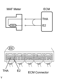
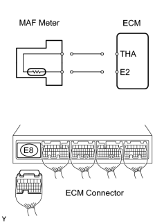
(a) Disconnect the M1 MAF meter connector. (b) Connect terminals THA and E2 of the E8 ECM connector. HINT: Before checking, do a visual and contact pressure check for the ECM connector. (c) Connect the intelligent tester to the CAN VIM. Then connect the CAN VIM to the DLC3. (d) Turn the ignition switch ON and turn the intelligent tester ON. (e) Enter the following menus: DIAGNOSIS / ENHANCED OBD II / DATA LIST / PRIMARY / INTAKE AIR. (f) Read the value. Standard: 140°C (284°F) or more |
|
| NG |
|
| OK |
|
|
4. |
READ VALUE USING INTELLIGENT TESTER (CHECK FOR SHORT IN WIRE HARNESS) |
|
(a) Disconnect the M1 MAF meter connector. (b) Connect the intelligent tester to the CAN VIM. Then connect the CAN VIM to the DLC3. (c) Turn the ignition switch ON and turn the intelligent tester ON. (d) Enter the following menus: DIAGNOSIS / ENHANCED OBD II / DATA LIST / PRIMARY / INTAKE AIR. (e) Read the value. Standard: -40°C (-40°F) or more |
|
| OK |
|
|
|
5. |
READ VALUE USING INTELLIGENT TESTER (CHECK FOR SHORT IN ECM) |
|
(a) Disconnect the M1 MAF meter connector. (b) Disconnect the E8 ECM connectors. (c) Connect the intelligent tester to the CAN VIM. Then connect the CAN VIM to the DLC3. (d) Turn the ignition switch ON and turn the intelligent tester ON. (e) Enter the following menus: DIAGNOSIS / ENHANCED OBD II / DATA LIST / PRIMARY / INTAKE AIR. (f) Read the value. Standard: -40°C (-40°F) or more |
|
| NG |
|
| OK |
|

|

|