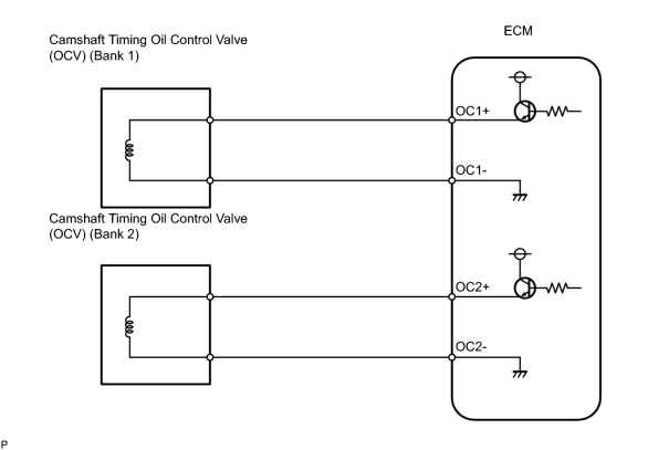
- Open or short in Oil control valve (OCV) (bank 1) circuit
- Oil control valve (OCV) (bank 1)
- ECM
| Last Modified: 4-30-2014 | 6.6 C | Doc ID: RM000000USA00BX |
| Model Year: 2006 | Model: LX470 | Prod Date Range: [05/2005 - ] |
| Title: 2UZ-FE ENGINE CONTROL SYSTEM: SFI SYSTEM: P0010,P0020; Camshaft Position "A" Actuator Circuit (Bank 1); 2006 MY LX470 [05/2005 - ] | ||
|
DTC |
P0010 |
Camshaft Position "A" Actuator Circuit (Bank 1) |
|
DTC |
P0020 |
Camshaft Position "A" Actuator Circuit (Bank 2) |
DESCRIPTION
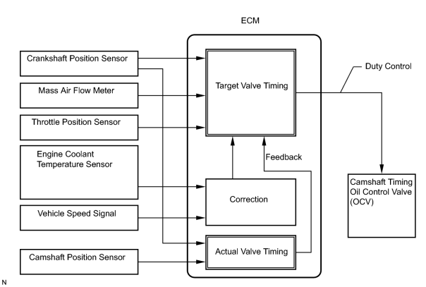
The Variable Valve Timing (VVT) system includes the ECM, Oil Control Valve (OCV) and VVT controller. The ECM sends a target duty-cycle control signal to the OCV. This control signal regulates the oil pressure supplied to the VVT controller. Camshaft timing control is performed according to engine operating conditions such as intake air volume, throttle valve position and engine coolant temperature.
The ECM controls the OCV, based on the signals transmitted by several sensors. The VVT controller regulates the intake camshaft angle using oil pressure through the OCV. As a result, the relative positions of the camshaft and crankshaft are optimized, the engine torque and fuel economy improve, and the exhaust emissions decrease under overall driving conditions. The ECM detects the actual intake valve timing using signals from the camshaft and crankshaft position sensors, and performs feedback control. This is how the target intake valve timing is verified by the ECM.
|
DTC No. |
DTC Detection Condition |
Trouble Area |
|---|---|---|
|
P0010 |
Open or short in Oil Control Valve (OCV) (bank 1) circuit (1 trip detection logic) |
|
|
P0020 |
Open or short in OCV (bank 2) circuit (1 trip detection logic) |
|
MONITOR DESCRIPTION
The ECM optimizes the valve timing using the VVT system to control the intake camshaft. The VVT system includes the ECM, the OCV and the VVT controller. The ECM sends a target duty-cycle control signal to the OCV. This control signal regulates the oil pressure supplied to the VVT controller. The VVT controller can advance or retard the intake camshaft.
After the ECM sends the "target" duty-cycle signal to the OCV, the ECM monitors the OCV current to establish an "actual" duty-cycle. The ECM detects a malfunction and sets a DTC when the actual duty-cycle ratio varies from the target duty-cycle ratio.
This monitor runs for 1 second (the first second of engine idle) after the engine is started.
MONITOR STRATEGY
|
Related DTCs |
P0010: OCV (bank 1) range check P0020: OCV (bank 2) range check |
|
Required Sensors/Components (Main) |
OCV |
|
Required Sensors/Components (Related) |
- |
|
Frequency of Operation |
Continuous |
|
Duration |
1 second |
|
MIL Operation |
Immediate |
|
Sequence of Operation |
None |
TYPICAL ENABLING CONDITIONS
|
Monitor will run whenever these DTCs are not present |
None |
|
All of the following conditions are met |
- |
|
Starter |
OFF |
|
Ignition switch |
ON |
|
Time after ignition switch OFF to ON |
0.5 seconds or more |
TYPICAL MALFUNCTION THRESHOLDS
|
One of the following conditions is met |
- |
|
A. All of the following conditions are met |
- |
|
a. Battery voltage |
11 V or more, and less than 13 V |
|
b. Target duty ratio |
Less than 70% |
|
c. Output signal duty ratio |
100% or more |
|
B. All of the following conditions are met |
- |
|
a. Battery voltage |
13 V or more |
|
b. Target duty ratio |
Less than 80% |
|
c. Output signal duty ratio |
100% or more |
|
C. Both of the following conditions are met |
- |
|
a. Current cut status |
Not cut |
|
b. Output signal duty ratio |
3% or less |
COMPONENT OPERATING RANGE
|
OCV current |
3 to 100% |
WIRING DIAGRAM
INSPECTION PROCEDURE
HINT:
- If DTC P0010 is displayed, check the bank 1 OCV.
- If DTC P0020 is displayed, check the bank 2 OCV.
- Bank 1 includes No. 1 cylinder, but bank 2 does not. No. 1 cylinder is located in the front part of the engine, opposite the transmission.
- Read freeze frame data using the intelligent tester. Freeze frame data records the engine conditions when malfunctions are detected. When troubleshooting, freeze frame data can help determine if the vehicle was running or stopped, if the engine was warmed up or not, if the air fuel ratio was lean or rich, and other data from the time the malfunction occurred.
PROCEDURE
|
1. |
PERFORM ACTIVE TEST (OCV) |
(a) Allow the engine to idle and warm up the engine.
(b) Using the intelligent tester, enter the following menus: DIAGNOSIS / ENHANCED OBD II / ACTIVE TEST / VVT CTRL B1 or VVT CTRL B2.
(c) Turn the oil control valve (OCV) on and check the engine speed.
OK:
|
Tester Operation |
Specified Condition |
|---|---|
|
OCV is OFF |
Normal engine speed |
|
OCV is ON |
Engine idles roughly or stalls (soon after OCV switched from OFF to ON) |
| NG |

|
| OK |
|
|
2. |
CHECK CAMSHAFT TIMING OIL CONTROL VALVE ASSEMBLY |
|
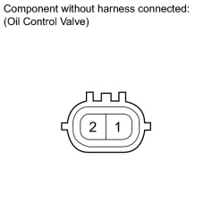
(a) Disconnect the camshaft oil control valve (OCV) connector. (b) Measure the resistance according to the value(s) in the table below. Standard:
|
|
| NG |
|
|

|
3. |
CHECK HARNESS AND CONNECTOR (OCV - ECM) |
(a)
Check harness and connector
![2006 MY LX470 [05/2005 - ]; INTRODUCTION: HOW TO TROUBLESHOOT ECU CONTROLLED SYSTEMS: ELECTRONIC CIRCUIT INSPECTION PROCEDURE](../../../../stylegraphics/info.gif "2006 MY LX470 [05/2005 - ]; INTRODUCTION: HOW TO TROUBLESHOOT ECU CONTROLLED SYSTEMS: ELECTRONIC CIRCUIT INSPECTION PROCEDURE") .
.
| NG |
|
| OK |
|

|

|