- Shift solenoid valve S2 remains open or closed
- Valve body is blocked
- Automatic transmission (clutch, brake or gear, etc.)
| Last Modified: 4-30-2014 | 6.6 C | Doc ID: RM000000W8000HX |
| Model Year: 2006 | Model: LX470 | Prod Date Range: [05/2005 - ] |
| Title: A750F AUTOMATIC TRANSMISSION: AUTOMATIC TRANSMISSION SYSTEM: P0756; Shift Solenoid "B" Performance (Shift Solenoid Valve S2); 2006 MY LX470 [05/2005 - ] | ||
|
DTC |
P0756 |
Shift Solenoid "B" Performance (Shift Solenoid Valve S2) |
DESCRIPTION
The ECM uses signals from the output shaft speed sensor and input speed sensor to detect the actual gear position (1st, 2nd, 3rd, 4th or 5th gear).
Then the ECM compares the actual gear with the shift schedule in the ECM memory to detect mechanical problems of the shift solenoid valves, valve body or automatic transmission (clutch, brake or gear, etc.).
|
DTC No. |
DTC Detection Condition |
Trouble Area |
|---|---|---|
|
P0756 |
Gear required by ECM does not match actual gear when driving (2 trip detection logic) |
|
MONITOR DESCRIPTION
This DTC indicates a stuck ON malfunction or stuck OFF malfunction of the shift solenoid valve S2.
The ECM commands gear shifts by turning the shift solenoid valves ON/OFF. When the gear position commanded by the ECM and the actual gear position are not the same, the ECM illuminates the MIL and stores the DTC.
MONITOR STRATEGY
|
Related DTCs |
P0756: Shift solenoid valve S2/OFF malfunction Shift solenoid valve S2/ON malfunction |
|
Required sensors/Components |
Shift solenoid valve S2, Vehicle speed sensor, Throttle position sensor, Speed sensor (NT), Speed sensor (NO) |
|
Frequency of operation |
Continuous |
|
Duration |
OFF malfunction (A), (B), (C) and ON malfunction (A), (B) 0.4 sec. OFF malfunction (D) Immediate ON malfunction (C) 3 sec. ON malfunction (D) 0.5 sec. |
|
MIL operation |
2 driving cycles |
|
Sequence of operation |
None |
TYPICAL ENABLING CONDITIONS
The following conditions are common to all conditions below.
|
The monitor will run whenever this DTC is not present. |
P0115 - P0118: ECT sensor P0125: Insufficient ECT for Closed Loop P0500: VSS P0748 - P798: Trans solenoid (range) |
|
Turbine speed sensor (NT) circuit |
Not circuit malfunction |
|
Output speed sensor (NO) circuit |
Not circuit malfunction |
|
Shift solenoid valve S1 circuit |
Not circuit malfunction |
|
Shift solenoid valve S2 circuit |
Not circuit malfunction |
|
Shift solenoid valve SR circuit |
Not circuit malfunction |
|
Shift solenoid valve SL1 circuit |
Not circuit malfunction |
|
Shift solenoid valve SL2 circuit |
Not circuit malfunction |
|
ECT (Engine coolant temperature) sensor circuit |
Not circuit malfunction |
|
KCS sensor circuit |
Not circuit malfunction |
|
ETCS (Electric throttle control system) |
Not system down |
|
Transmission range |
"D" |
|
ECT |
40°C (104°F) or more |
|
Spark advance from Max. retard timing by KCS control |
0°crankshaft angle or more |
|
Engine |
Starting |
|
Transfer range |
"HIGH" * |
Transfer range "HIGH" * (This condition is applied only 4WD)
* Following conditions met|
Vehicle speed sensor "A" circuit |
Not circuit malfunction |
|
Output shaft speed sensor circuit |
Not circuit malfunction |
|
Transfer output speed |
143 rpm or more |
|
NO/NOtf (Transfer input speed/Transfer output speed) |
0.9 to 1.1 |
OFF malfunction (A)
|
ECM selected gear |
1st |
|
Vehicle speed |
2 to 40 km/h (1.2 to 24.9 mph) |
|
Throttle valve opening angle |
7% or more at 2,000 rpm (Conditions vary with engine speed) |
OFF malfunction (B)
|
ECM selected gear |
2nd |
|
Vehicle speed |
2 km/h (1.2 mph) or more |
|
Output speed |
2nd → 1st down shift point or more |
|
Throttle valve opening angle |
7% or more at 2,000 rpm (Conditions vary with engine speed) |
OFF malfunction (C)
|
Current ECM selected gear |
5th |
|
Last ECM selected gear |
4th |
|
Continuous time for ECM selecting 4th gear |
2 sec. or more |
|
Actual gear when ECM selected 4th gear |
4th |
OFF malfunction (D)
|
Current ECM selected gear |
5th |
|
Last ECM selected gear |
4th |
ON malfunction (A)
|
ECM selected gear |
1st |
|
Vehicle speed |
2 to 40 km/h (1.2 to 24.9 mph) |
|
Throttle valve opening angle |
7% or more at 2,000 rpm (Conditions vary with engine speed) |
|
Calculated load value |
7.75% or more |
ON malfunction (B)
|
ECM selected gear |
4th |
|
Vehicle speed |
2 km/h (1.2 mph) or more |
|
Throttle valve opening angle |
7% or more at 2,000 rpm (Conditions vary with engine speed) |
|
Calculated load value |
7.75% or more |
ON malfunction (C)
|
Current ECM selected gear |
5th |
|
Last ECM selected gear |
4th |
|
Vehicle speed |
Less than 100 km/h (62.2 mph) |
ON malfunction (D)
|
ECM selected gear |
5th |
|
Vehicle speed |
Less than 100 km/h (62.2 mph) |
TYPICAL MALFUNCTION THRESHOLDS
OFF malfunction:
All of the following are met: Conditions (A), (B), (C) and (D)
2 detections are necessary per driving cycle:
1st detection; temporary flag ON
2nd detection; pending fault code ON
OFF malfunction (A) and (B)
|
Turbine speed/Output speed (NT/NO) |
3.30 to 7.50 |
OFF malfunction (C)
|
Turbine speed/Output speed (NT/NO) |
0.65 to 0.79 |
OFF malfunction (D)
|
Output record from ECM for 4th → 5th upshifting |
Recorded |
ON malfunction:
Both of the following conditions are met: ON malfunction (A) or (B), and ON malfunction (C) or (D)
ON malfunction (A)
|
Turbine speed/Output speed (NT/NO) |
1.91 to 2.35 |
ON malfunction (B)
|
Turbine speed/Output speed (NT/NO) |
1.28 to 1.53 |
ON malfunction (C)
|
Turbine speed - Output speed x 4th gear ratio (NT - NO x 4th gear ratio) |
1,000 rpm or more |
ON malfunction (D)
|
Turbine speed - Output speed x 5th gear ratio (NT - NO x 5th gear ratio) |
1,000 rpm or more |
INSPECTION PROCEDURE
HINT:
Performing the intelligent tester's ACTIVE TEST allows relay, VSV, actuator and other items to be operated without removing any parts. Performing the ACTIVE TEST early in troubleshooting is one way to save time.
The DATA LIST can be displayed during the ACTIVE TEST.
- Warm up the engine.
- Turn the ignition switch OFF.
- Connect the intelligent tester to the CAN VIM. Then connect the CAN VIM to the DLC3.
- Turn the ignition switch ON.
- Turn the intelligent tester ON.
- Enter the following menus: DIAGNOSIS / ENHANCED OBD II / ACTIVE TEST.
- Follow the instructions on the tester and read the ACTIVE TEST.
HINT:
While driving, the shift position can be forcibly changed with the intelligent tester.
Comparing the shift position commanded by the ACTIVE TEST with the actual shift position enables you to confirm the problem
![2006 MY LX470 [05/2005 - ]; A750F AUTOMATIC TRANSMISSION: AUTOMATIC TRANSMISSION SYSTEM: FAIL-SAFE CHART](../../../../stylegraphics/info.gif "2006 MY LX470 [05/2005 - ]; A750F AUTOMATIC TRANSMISSION: AUTOMATIC TRANSMISSION SYSTEM: FAIL-SAFE CHART") .
.
|
Item |
Test Details |
Diagnostic Note |
|---|---|---|
|
SHIFT |
[Test Details] Operate the shift solenoid valve and set each shift position by yourself [Vehicle Condition]
[Other information]
|
Possible to check the operation of the shift solenoid valves |
HINT:
- This test can be conducted when the vehicle speed is 50 km/h (31 mph) or less.
- The 4th to 5th up-shift must be performed with the accelerator pedal released.
- The 5th to 4th down-shift must be performed with the accelerator pedal released.
- Do not operate the accelerator pedal for at least 2 seconds after shifting and do not shift successively.
- The shift position commanded by the ECM is shown in the DATA LIST (shift status) display on the intelligent tester.
-
The shift solenoid valve S2 is turned ON/OFF normally when the shift lever is on D:
ECM gear shift command
1st
2nd
3rd
4th
5th
Shift solenoid valve S2
OFF
ON
ON
OFF
OFF
PROCEDURE
|
1. |
CHECK OTHER DTCS OUTPUT (IN ADDITION TO DTC P0756) |
(a) Connect the intelligent tester to the CAN VIM. Then connect the CAN VIM to the DLC3.
(b) Turn the ignition switch ON and push the intelligent tester main switch ON.
(c) Enter the following menus: DIAGNOSIS / ENHANCED OBD II / DTC INFO / CURRENT CODES.
(d) Read the DTCs using the intelligent tester.
|
Display (DTC output) |
Proceed to |
|---|---|
|
Only P0756 is output |
A |
|
P0756 and other DTCs |
B |
HINT:
If any other codes besides P0756 are output, perform troubleshooting for those DTCs first.
| B |

|
|

|
2. |
INSPECT SHIFT SOLENOID VALVE S2 |
|
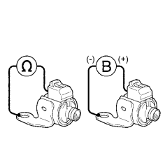
(a) Remove the shift solenoid valve S2. |
|
(b) Measure the resistance between the solenoid valve terminal and solenoid valve body.
Standard resistance:
11 to 15 Ω at 20°C (68°F)
(c) Connect the battery's positive (+) lead to the terminal of the solenoid connector, and the negative (-) lead to the solenoid body.
OK:
Solenoid makes an operating noise.
| NG |
|
|
|
3. |
INSPECT TRANSMISSION VALVE BODY ASSEMBLY |
OK:
There are no foreign objects on each valve.
| NG |
|
| OK |
|

|

|