- All switches are OFF simultaneously for P, R, N, D, 3 and 2 positions
| Last Modified: 4-30-2014 | 6.6 C | Doc ID: RM000000W8400KX |
| Model Year: 2006 | Model: LX470 | Prod Date Range: [05/2005 - ] |
| Title: A750F AUTOMATIC TRANSMISSION: AUTOMATIC TRANSMISSION SYSTEM: P0705; Transmission Range Sensor Circuit Malfunction (PRNDL Input); 2006 MY LX470 [05/2005 - ] | ||
|
DTC |
P0705 |
Transmission Range Sensor Circuit Malfunction (PRNDL Input) |
DESCRIPTION
The Park/Neutral Position (PNP) switch detects the shift lever position and sends signals to the ECM.
|
DTC No. |
DTC Detection Condition |
Trouble Area |
|---|---|---|
|
P0705 |
When either condition below is met (2 trip detection logic):
|
|
MONITOR DESCRIPTION
These DTCs indicate a problem with the PNP switch and the wire harness in the PNP switch circuit.
The PNP switch detects the shift lever position and sends a signal to the ECM.
For security, the PNP switch detects the shift lever position so that the engine can be started only when the shift lever is on P or N.
The PNP switch sends a signal to the ECM according to the shift lever position (R, D, 4, 3, 2 or L).
The ECM determines that there is a problem with the switch or related parts if it receives more than 1 position signal simultaneously. The ECM will illuminate the MIL and store the DTC.
MONITOR STRATEGY
|
Related DTCs |
P0705: Park/Neutral position switch/Verify switch input |
|
Required sensors/Components |
Park/Neutral position switch |
|
Frequency of operation |
Continuous |
|
Duration |
Condition (A), (B) and (D) 2 sec. Condition (C) 60 sec. |
|
MIL operation |
2 driving cycles |
|
Sequence of operation |
None |
TYPICAL ENABLING CONDITIONS
|
The monitor will run whenever this DTC is not present. |
None |
|
Ignition switch |
ON |
|
Battery voltage |
10.5 V or more |
TYPICAL MALFUNCTION THRESHOLDS
One of the following conditions is met: Condition (A), (B), (C) or (D)
Condition (A)
|
Number of the following signal inputs at the same time |
2 or more |
|
P switch |
ON |
|
N switch |
ON |
|
R switch |
ON |
|
D switch |
ON |
|
3 switch |
ON |
|
2 switch |
ON |
Condition (B)
|
Number of the following signal inputs at the same time |
2 or more |
|
NSW switch |
OFF |
|
R switch |
ON |
|
D switch |
ON |
|
3 switch |
ON |
|
2 switch |
ON |
Condition (C)
All of the following conditions are met|
P switch |
OFF |
|
N switch |
OFF |
|
NSW switch |
OFF |
|
R switch |
OFF |
|
D switch |
OFF |
|
3 switch |
OFF |
|
2 switch |
OFF |
Condition (D)
Both (i) and (ii) are met (i) One of the following conditions is met|
NSW switch |
ON |
|
P switch |
ON |
|
N switch |
ON |
|
R switch |
ON |
(ii) One of the following conditions is met
|
4 switch |
ON |
|
L switch |
ON |
COMPONENT OPERATING RANGE
|
Park/Neutral position switch |
Park/Neutral position switch sends only one signal to the ECM. |
WIRING DIAGRAM
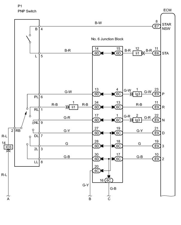
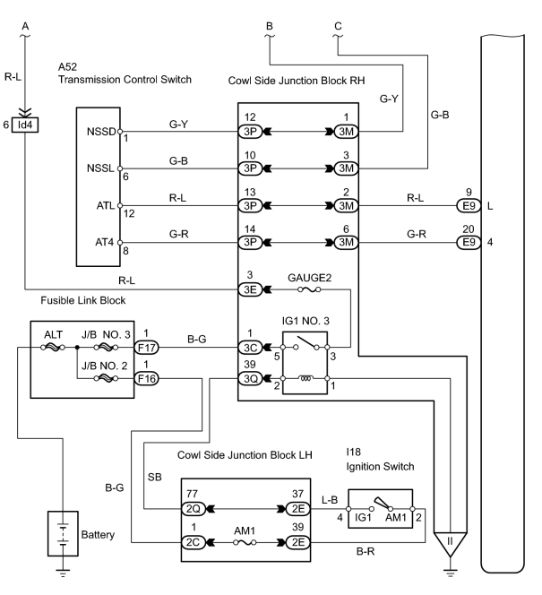
INSPECTION PROCEDURE
HINT:
Using the intelligent tester's DATA LIST allows switch, sensor, actuator and other item values to be read without removing any parts. Reading the DATA LIST early in troubleshooting is one way to save time.
NOTICE:
In the table below, the values listed under "Normal Condition" are reference values. Do not depend solely on these reference values when deciding whether a part is faulty or not.
- Warm up the engine.
- Turn the ignition switch OFF.
- Connect the intelligent tester to the CAN VIM. Then connect the CAN VIM to the DLC3.
- Turn the ignition switch ON.
- Turn the intelligent tester ON.
- Enter the following menus: DIAGNOSIS / ENHANCED OBD II / DATA LIST.
- Follow the instructions on the tester and read the DATA LIST.
|
Item |
Measurement Item/ Range (Display) |
Normal Condition |
Diagnostic Note |
|---|---|---|---|
|
PNP SW (NSW) |
PNP switch status/ ON or OFF |
Shift lever is: On P or N: ON Not on P or N: OFF |
When shift lever position displayed on intelligent tester differs from actual position, adjustment of PNP switch or shift cable may be incorrect |
|
LOW |
PNP switch status/ ON or OFF |
Shift lever is: On L: ON Not on L: OFF |
When shift lever position displayed on intelligent tester differs from actual position, adjustment of PNP switch or shift cable may be incorrect |
|
2ND |
PNP switch status/ ON or OFF |
Shift lever is: On 2: ON Not on 2: OFF |
When shift lever position displayed on intelligent tester differs from actual position, adjustment of PNP switch or shift cable may be incorrect |
|
3RD |
PNP switch status/ ON or OFF |
Shift lever is: On 3: ON Not on 3: OFF |
When shift lever position displayed on intelligent tester differs from actual position, adjustment of PNP switch or shift cable may be incorrect |
|
4th/DRIVE |
PNP switch status/ ON or OFF |
Shift lever is: On 4: ON Not on 4: OFF |
When shift lever position displayed on intelligent tester differs from actual position, adjustment of PNP switch or shift cable may be incorrect |
|
REVERSE |
PNP switch status/ ON or OFF |
Shift lever is: On R: ON Not on R: OFF |
When shift lever position displayed on intelligent tester differs from actual position, adjustment of PNP switch or shift cable may be incorrect |
|
DRIVE |
PNP switch status/ ON or OFF |
Shift lever is: On D: ON Not on D: OFF |
When shift lever position displayed on intelligent tester differs from actual position, adjustment of PNP switch or shift cable may be incorrect |
PROCEDURE
|
1. |
INSPECT PARK/NEUTRAL POSITION SWITCH |
|
(a) Disconnect the P1 PNP switch connector. |
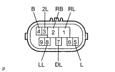
|
(b) Measure the resistance of the PNP switch when the shift lever is moved to each position.
Standard resistanc:
|
Tester Connection |
Shift Lever Position |
Specified Condition |
|---|---|---|
|
4 (B) - 5 (L) |
P or N |
Below 1 Ω |
|
4 (B) - 5 (L) |
Not on P or N |
10 kΩ or higher |
|
1 (RL) - 2 (RB) |
R |
Below 1 Ω |
|
1 (RL) - 2 (RB) |
Not on R |
10 kΩ or higher |
|
2 (RB) - 7 (DL) |
D |
Below 1 Ω |
|
2 (RB) - 7 (DL) |
Not on D |
10 kΩ or higher |
|
2 (RB) - 3 (2L) |
2 |
Below 1 Ω |
|
2 (RB) - 3 (2L) |
Not on 2 |
10 kΩ or higher |
|
2 (RB) - 8 (LL) |
L |
Below 1 Ω |
|
2 (RB) - 8 (LL) |
Not on L |
10 kΩ or higher |
| NG |

|
|

|
2. |
INSPECT TRANSMISSION CONTROL SWITCH |
|
(a) Disconnect the A52 switch connector. |
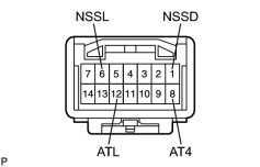
|
(b) Measure the resistance of the switch when the shift lever is moved to each position.
Standard resistance:
|
Tester Connection |
Shift Lever Position |
Specified Condition |
|---|---|---|
|
1 (NSSD) - 8 (AT4) |
D |
10 kΩor higher |
|
1 (NSSD) - 8 (AT4) |
3 |
Below 1 Ω |
|
6 (NSSL) - 12 (ATL) |
2 |
10 kΩ or higher |
|
6 (NSSL) - 12 (ATL) |
L |
Below 1 Ω |
| NG |
|
|
|
3. |
CHECK WIRE HARNESS (ECM - BATTERY) |
|
(a) Turn the ignition switch ON. (b) Measure the voltage of the wire harness side connector. Standard voltage:
HINT: *: The voltage will drop slightly due to the illumination of the back-up light. |
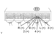
|
| NG |
|
| OK |
|

|

|