- Open or short in shift solenoid valve SLU circuit
- Shift solenoid valve SLU
- ECM
| Last Modified: 4-30-2014 | 6.6 C | Doc ID: RM000000W8900HX |
| Model Year: 2006 | Model: LX470 | Prod Date Range: [05/2005 - ] |
| Title: A750F AUTOMATIC TRANSMISSION: AUTOMATIC TRANSMISSION SYSTEM: P2759; Torque Converter Clutch Pressure Control Solenoid Control Circuit Electrical (Shift Solenoid Valve SLU); 2006 MY LX470 [05/2005 - ] | ||
|
DTC |
P2759 |
Torque Converter Clutch Pressure Control Solenoid Control Circuit Electrical (Shift Solenoid Valve SLU) |
DESCRIPTION
The amount of current flow to the solenoid is controlled by the duty ratio* of the ECM output signal. The higher the duty ratio becomes, the higher the lock-up hydraulic pressure becomes during the lock-up operation.
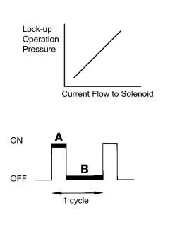
*: The duty ratio is the ratio of the current ON time (A) to the total of the current ON and OFF times (A + B).
Duty Ratio (%) = A / (A + B) x 100
|
DTC No. |
DTC Detection Condition |
Trouble Area |
|---|---|---|
|
P2759 |
Open or short is detected in shift solenoid valve SLU circuit for 1 second or more while driving (1 trip detection logic) |
|
|
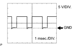
1. Reference: Inspect using an oscilloscope. Check the waveform of the ECM connector. Standard voltage: Refer to illustration.
|
|
MONITOR DESCRIPTION
When an open or short in a shift solenoid valve SLU circuit is detected, the ECM determines that there is a malfunction. The ECM will illuminate the MIL and store this DTC.
MONITOR STRATEGY
|
Related DTCs |
P2759: Shift solenoid valve SLU/Range check |
|
Required sensors/Components |
Shift solenoid valve SLU |
|
Frequency of operation |
Continuous |
|
Duration |
1 sec. |
|
MIL operation |
Immediate |
|
Sequence of operation |
None |
TYPICAL ENABLING CONDITIONS
|
The monitor will run whenever this DTC is not present. |
None |
|
Solenoid current cut status |
Not cut |
|
CPU commanded duty |
19% or more |
|
Battery voltage |
11 V or more |
|
Ignition switch |
ON |
|
Starter |
OFF |
TYPICAL MALFUNCTION THRESHOLDS
|
Solenoid status (SLU) from MIC |
Fail |
COMPONENT OPERATING RANGE
|
Output signal duty |
Less than 100% |
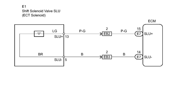
WIRING DIAGRAM
INSPECTION PROCEDURE
PROCEDURE
|
1. |
INSPECT TRANSMISSION WIRE (SHIFT SOLENOID VALVE SLU) |
|
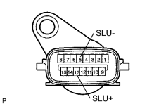
(a) Disconnect the E1 wire connector. |
|
(b) Measure the resistance of the transmission wire.
Standard resistance:
|
Tester Connection |
Condition |
Specified Condition |
|---|---|---|
|
13 (SLU+) - 5 (SLU-) |
20°C (68°F) |
5.0 to 5.6 Ω |
|
13 (SLU+) - Body ground |
20°C (68°F) |
10 kΩ or higher |
|
5 (SLU-) - Body ground |
20°C (68°F) |
10 kΩ or higher |
| NG |

|
|

|
2. |
CHECK WIRE HARNESS (TRANSMISSION WIRE - ECM) |
|
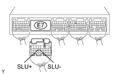
(a) Disconnect the E7 ECM connector. |
|
(b) Measure the resistance of the wire harness side connector.
Standard resistance:
|
Tester Connection |
Condition |
Specified Condition |
|---|---|---|
|
E7-15 (SLU+) - E7-14 (SLU-) |
20°C (68°F) |
5.0 to 5.6 Ω |
|
E7-15 (SLU+) - Body ground |
20°C (68°F) |
10 kΩ or higher |
|
E7-14 (SLU-) - Body ground |
20°C (68°F) |
10 kΩ or higher |
| NG |
|
| OK |
|
|
3. |
INSPECT SHIFT SOLENOID VALVE SLU |
|
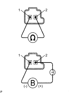
(a) Remove the shift solenoid valve SLU. (b) Measure the resistance of the solenoid valve. Standard resistance: 5.0 to 5.6 Ωat 20°C (68°F) (c) Connect the battery's positive (+) lead to the terminal of the solenoid connector, and the negative (-) lead to the solenoid body. OK: Solenoid makes operating noise. |
|
| NG |
|
| OK |
|

|

|