- Gas leakage from exhaust system
- Air Fuel Ratio (A/F) sensor (bank 1 sensor 1)
- Heated Oxygen (HO2) sensor (bank 1 sensor 2)
- Front exhaust pipe LH (TWC: Front and rear catalyst)
| Last Modified: 4-30-2014 | 6.6 C | Doc ID: RM000000WC000FX |
| Model Year: 2006 | Model: LX470 | Prod Date Range: [05/2005 - ] |
| Title: 2UZ-FE ENGINE CONTROL SYSTEM: SFI SYSTEM: P0420,P0430; Catalyst System Efficiency Below Threshold (Bank 1); 2006 MY LX470 [05/2005 - ] | ||
|
DTC |
P0420 |
Catalyst System Efficiency Below Threshold (Bank 1) |
|
DTC |
P0430 |
Catalyst System Efficiency Below Threshold (Bank 2) |
MONITOR DESCRIPTION
The ECM uses sensors mounted in front of and behind the Three-way Catalytic Converter (TWC) to monitor its efficiency.
The first sensor, the Air Fuel Ratio (A/F) sensor, sends pre-catalyst information to the ECM. The second sensor, the Heated Oxygen (HO2) sensor, sends post-catalyst information to the ECM.
In order to detect any deterioration in the TWC, the ECM calculates the Oxygen Storage Capacity (OSC) of the TWC. This calculation is based on the voltage output of the HO2 sensor while performing active air-fuel ratio control, rather than the conventional detecting method, which uses the locus ratio.
The OSC value is an indication of the oxygen storage capacity of the TWC. When the vehicle is being driven with a warm engine, active air fuel ratio control is performed for approximately 15 to 20 seconds. When it is performed, the ECM deliberately sets the air fuel ratio to lean or rich levels. If a rich-lean cycle of the HO2 sensor is long, the OSC becomes greater. There is a direct correlation between the OSCs of the HO2 sensor and the TWC.
The ECM uses the OSC value to determine the state of the TWC. If any deterioration has occurred, it illuminates the MIL and sets a DTC.
|
DTC No. |
DTC Detection Condition |
Trouble Area |
|---|---|---|
|
P0420 |
OSC value smaller than standard value under active air fuel ratio control (2 trip detection logic) |
|
|
P0430 |
OSC value smaller than standard value under active air fuel ratio control (2 trip detection logic) |
|
HINT:
- Bank 1 refers to the bank that includes No. 1 cylinder.
- Bank 2 refers to the bank that does not include No. 1 cylinder.
- Sensor 1 refers to the sensor closest to the engine assembly.
- Sensor 2 refers to the sensor farthest away from the engine assembly.
MONITOR STRATEGY
|
Related DTCs |
P0420: Catalyst (Bank 1) detection P0430: Catalyst (Bank 2) detection |
|
Required Sensors/Components (Main) |
Catalyst |
|
Required Sensors/Components (Related) |
Heated oxygen sensor, Intake air temperature sensor, Mass air flow meter, Crankshaft position sensor, Engine coolant temperature sensor |
|
Frequency of Operation |
Unified cycle |
|
Duration |
About 30 seconds |
|
MIL Operation |
2 driving cycles |
|
Sequence of Operation |
None |
TYPICAL ENABLING CONDITIONS
|
The monitor will run whenever these DTCs are not present |
P0011 (VVT System 1 - Advance) P0012 (VVT System 1 - Retard) P0021 (VVT System 2 - Advance) P0022 (VVT System 2 - Retard) P0031, P0032, P0051, P0052 (A/F sensor heater - Sensor 1) P0037, P0038, P0057, P0058 (HO2 sensor Heater - Sensor 2) P0100 - P0103 (MAF meter) P0115 - P0118 (ECT sensor) P0120 - P0223, P2135 (TP sensor) P0125 (Insufficient ECT for closed loop) P0136, P0156 (HO2 Sensor - Sensor 2) P0171, P0172 (Fuel system) P0300 - P0308 (Misfire) P0335 (CKP sensor) P0340, P0341 (CMP sensor) P0351 - P0356 (Ignitor) P0500 (VSS) P2196, P2198 (A/F sensor - rationality) P2440 (A/R control valve stuck open) P2441 (A/R control valve stuck close) P2444 (AIP stuck ON) P2445 (AIP stuck OFF) P2A00, P2A03 (A/F sensor - slow response) |
|
Battery voltage |
11 V or more |
|
Intake air temperature |
-10°C (14°F) or more |
|
Engine coolant temperature |
75°C (167°F) or more |
|
Atmospheric pressure coefficient |
0.75 or more |
|
Idle |
OFF |
|
Engine RPM |
Less than 3,200 rpm |
|
A/F sensor |
Activated |
|
Fuel system status |
Closed-loop |
|
Engine load |
10 to 70% |
|
All of the following conditions are met |
Conditions 1, 2 and 3 |
|
1. MAF |
6 to 25 g/sec. (Varies with engine RPM) |
|
2. Front catalyst temperature (estimated) |
410 to 830°C (770 to 1,526°F) (Varies with MAF) |
|
3. Rear catalyst temperature (estimated) |
410 to 830°C (770 to 1,526°F) (Varies with MAF) |
|
Rear HO2S heater monitor |
Completed |
|
Shift position |
4th or more |
TYPICAL MALFUNCTION THRESHOLDS
|
Oxygen storage capacity (OSC) of catalyst |
Less than 0.16 g |
MONITOR RESULT
Detailed information on Checking Monitor Status
![2006 MY LX470 [05/2005 - ]; 2UZ-FE ENGINE CONTROL SYSTEM: SFI SYSTEM: CHECKING MONITOR STATUS](../../../../stylegraphics/info.gif "2006 MY LX470 [05/2005 - ]; 2UZ-FE ENGINE CONTROL SYSTEM: SFI SYSTEM: CHECKING MONITOR STATUS") .
.
The vest value and test limit information are in the following table. Check the monitor result and test values after performing the monitor drive pattern (refer to "Confirmation Monitor").
- Monitor Identification Data (MID) is assigned to each emissions-related component.
- Test Identification Data (TID) is assigned to each test value.
- Scaling is used to calculate the test value indicated on generic OBD II scan tools.
Catalyst bank 1 - Active A/F control method
|
MID |
TID |
Scaling |
Description of Test Value |
Minimum Test Limit |
Maximum Test Limit |
|---|---|---|---|---|---|
|
$21 |
$A9 |
Multiply by 0.0003 (no dimension) |
Oxygen storage capacity of catalyst |
Minimum test limit for catalyst |
Maximum test limit for catalyst |
Catalyst bank 2 - Active A/F control method
|
MID |
TID |
Scaling |
Description of Test Value |
Minimum Test Limit |
Maximum Test Limit |
|---|---|---|---|---|---|
|
$22 |
$A9 |
Multiply by 0.0003 (no dimension) |
Oxygen storage capacity of catalyst |
Minimum test limit for catalyst |
Maximum test limit for catalyst |
CONDITIONING FOR SENSOR TESTING
HINT:
Perform the operation with the engine speeds and time durations described below prior to checking the waveforms of the A/F and HO2 sensors. This is in order to activate the sensors sufficiently to obtain the appropriate inspection results.
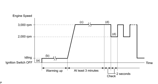
- (a) Connect the intelligent tester to the CAN VIM. Then connect the CAN VIM to the DLC3.
- (b) Start the engine and warm it up with all the accessories switched OFF, until the engine coolant temperature stabilizes.
- (c) Run the engine at engine speed of between 2,500 rpm and 3,000 rpm for at least 3 minutes.
-
(d) While running the engine at 3,000 rpm for 2 seconds and 2,000 rpm for 2 seconds, check the waveforms of the A/F and HO2 sensors using the tester.
HINT:
- If either of voltage outputs of the Air Fuel Ratio (A/F) or Heated Oxygen (HO2) sensors does not fluctuate, or either of the sensors makes a noise, the sensor may be malfunctioning.
- If the voltage outputs of both the sensors remain lean or rich, the air fuel ratio may be extremely lean or rich. In such cases, perform the following A/F CONTROL using the intelligent tester.
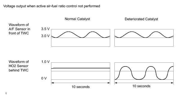
- If the Three-Way Catalytic Converter (TWC) has deteriorated, the HO2 sensor (located behind the TWC) voltage output fluctuates up and down frequently, even under normal driving conditions (active air fuel ratio control is not performed).
1. A/F CONTROL
HINT:
Intelligent tester only:
Malfunctioning areas can be identified by performing the A/F CONTROL function provided in the ACTIVE TEST. The A/F CONTROL function can help to determine whether the Air Fuel Ratio (A/F) sensor, Heated Oxygen (HO2) sensor and other potential trouble areas are malfunctioning.
The following instructions describe how to conduct the A/F CONTROL operation using the intelligent tester.
- Connect the intelligent tester to the CAN VIM. Then connect the CAN VIM to the DLC3.
- Start the engine and turn the tester ON.
- Warm up the engine at engine speed of 2,500 rpm for approximately 90 seconds.
- On the tester, enter the following menus: DIAGNOSIS / ENHANCED OBD II / ACTIVE TEST / A/F CONTROL.
- Perform the A/F CONTROL operation with the engine in an idling condition (press the RIGHT or LEFT button to change the fuel injection volume).
- Monitor the voltage outputs of the A/F and HO2 sensors (AFS B1S1 and O2S B1S2 or AFS B2S1 and O2S B2S2) displayed on the tester.
HINT:
- The A/F CONTROL operation lowers the fuel injection volume by 12.5% or increases the injection volume by 25%.
- Each sensor reacts in accordance with increases in the fuel injection volume.
Standard:
|
Tester Display (Sensor) |
Injection Volume |
Status |
Voltage |
|---|---|---|---|
|
AFS B1S1 or AFS B2S1 (A/F) |
+25% |
Rich |
Less than 3.0 |
|
AFS B1S1 or AFS B2S1 (A/F) |
-12.5% |
Lean |
More than 3.35 |
|
O2S B1S2 or O2S B2S2 (HO2) |
+25% |
Rich |
More than 0.55 |
|
O2S B1S2 or O2S B2S2 (HO2) |
-12.5% |
Lean |
Less than 0.4 |
NOTICE:
The Air Fuel Ratio (A/F) sensor has an output delay of a few seconds and the Heated Oxygen (HO2) sensor has a maximum output delay of approximately 20 seconds.
|
Case |
A/F Sensor (Sensor 1) Output Voltage |
HO2 Sensor (Sensor 2) Output Voltage |
Main Suspected Trouble Area |
||
|---|---|---|---|---|---|
|
1 |
Injection Volume +25% -12.5% |

|
Injection Volume +25% -12.5% |
|
- |
|
Output Voltage More than 3.35 V Less than 3.0 V |

|
Output Voltage More than 0.55 V Less than 0.4 V |

|
||
|
2 |
Injection Volume +25% -12.5% |
|
Injection Volume +25% -12.5% |
|
|
|
Output Voltage Almost no reaction |
|
Output Voltage More than 0.55 V Less than 0.4 V |
|
||
|
3 |
Injection Volume +25% -12.5% |
|
Injection Volume +25% -12.5% |
|
|
|
Output Voltage More than 3.35 V Less than 3.0 V |
|
Output Voltage Almost no reaction |
|
||
|
4 |
Injection volume +25% -12.5% |
|
Injection Volume +25% -12.5% |
|
|
|
Output Voltage Almost no reaction |
|
Output Voltage Almost no reaction |
|
||
- Following the A/F CONTROL procedure enables technicians to check and graph the output voltages of both the A/F and HO2 sensors.
- To display the graph, enter the following menus on the tester: DIAGNOSIS / ENHANCED OBD II / ACTIVE TEST / A/F CONTROL / USER DATA / AFS B1S1 and O2S B1S2 or AFS B2S1 and O2S B2S2. Then press the YES button and ENTER button, followed by the F4 button.
INSPECTION PROCEDURE
HINT:
Read freeze frame data using the intelligent tester. Freeze frame data records the engine conditions when malfunctions are detected. When troubleshooting, freeze frame data can help determine if the vehicle was running or stopped, if the engine was warmed up or not, if the air fuel ratio was lean or rich, and other data from the time the malfunction occurred.
PROCEDURE
|
1. |
CHECK ANY OTHER DTCS OUTPUT (IN ADDITION TO DTC P0420 AND/OR P0430) |
(a) Connect the intelligent tester to the CAN VIM. Then connect the CAN VIM to the DLC3.
(b) Turn the ignition switch ON and turn the tester ON.
(c) Enter the following menus: DIAGNOSIS / ENHANCED OBD II / DTC INFO / CURRENT CODES.
(d) Read DTCs.
|
Display (DTC output) |
Proceed to |
|---|---|
|
P0420 and/or P0430 |
A |
|
P0420 and/or P0430 and other DTCs |
B |
HINT:
If any DTCs other than P0420 or P0430 are output, troubleshoot those DTCs first.
| B |

|
|

|
2. |
PERFORM ACTIVE TEST USING INTELLIGENT TESTER (A/F CONTROL) |
- Connect the intelligent tester to the CAN VIM. Then connect the CAN VIM to the DLC3.
- Start the engine and turn the tester ON.
- Warm up the engine at engine speed of 2,500 rpm for approximately 90 seconds.
- On the tester, enter the following menus: DIAGNOSIS / ENHANCED OBD II / ACTIVE TEST / A/F CONTROL.
- Perform the A/F CONTROL operation with the engine in an idling condition (press the RIGHT or LEFT button to change the fuel injection volume).
- Monitor the output voltages of the A/F and HO2 sensors (AFS B1S1 and O2S B1S2 or AFS B2S1 and O2S B2S2) displayed on the tester.
HINT:
- The A/F CONTROL operation lowers the fuel injection volume by 12.5% or increases the injection volume by 25%.
- Each sensor reacts in accordance with increases and decreases in the fuel injection volume.
Standard:
|
Tester Display (Sensor) |
Injection Volume |
Status |
Voltage |
|---|---|---|---|
|
AFS B1S1 or AFS B2S1 (A/F) |
+25% |
Rich |
Less than 3.0 |
|
AFS B1S1 or AFS B2S1 (A/F) |
-12.5% |
Lean |
More than 3.35 |
|
O2S B1S2 or O2S B2S2 (HO2) |
+25% |
Rich |
More than 0.55 |
|
O2S B1S2 or O2S B2S2 (HO2) |
-12.5% |
Lean |
Less than 0.4 |
Result:
|
Status AFS B1S1 or AFS B2S1 |
Status O2S B1S2 or O2S B2S2 |
A/F Condition and A/F and HO2 Sensor Conditions |
Misfire |
Main Suspected Trouble Areas |
Proceed to |
|---|---|---|---|---|---|
|
Lean/Rich |
Lean/Rich |
Normal |
- |
|
A |
|
Lean |
Lean/Rich |
A/F sensor malfunction |
- |
|
B |
|
Rich |
Lean/Rich |
A/F sensor malfunction |
May occur |
|
B |
|
Lean/Rich |
Lean |
HO2 sensor malfunction |
- |
|
C |
|
Lean/Rich |
Rich |
HO2 sensor malfunction |
- |
|
C |
|
Lean |
Lean |
Actual air fuel ratio lean |
May occur |
|
A |
|
Rich |
Rich |
Actual air fuel ratio lean |
- |
|
A |
Lean: During A/F CONTROL, the A/F sensor (AFS) output voltage is consistently more than 3.35 V, and the HO2 sensor output voltage (O2S) is consistently less than 0.4 V.
Rich: During A/F CONTROL, the AFS is consistently less than 3.0 V, and the O2S is consistently more than 0.55 V.
Lean/Rich: During A/F CONTROL, the output voltage of the HO2 sensor alternates correctly.
| B |
|
| C |
|
CHECK AND REPLACE HEATED OXYGEN SENSOR, AND CHECK AND REPAIR EXHAUST GAS LEAKAGE |
|
|
3. |
CHECK FOR EXHAUST GAS LEAKAGE |
OK:
No gas leakage.
| NG |
|
|
|
4. |
CHECK DTC OUTPUT (DTC P0420 AND/OR P0430) |
(a) Connect the intelligent tester to the CAN VIM. Then connect the CAN VIM to the DLC3.
(b) Turn the ignition switch ON and turn the tester ON.
(c) Enter the following menus: DIAGNOSIS / ENHANCED OBD II / DTC INFO / CURRENT CODES.
(d) Read DTCs.
|
Display (DTC output) |
Proceed to |
|---|---|
|
P0420 |
A |
|
P0430 |
B |
|
P0420 and P0430 |
A and B |
| B |
|
REPLACE FRONT EXHAUST PIPE RH (TWC: FRONT AND REAR CATALYST) |
| A |
|
REPLACE FRONT EXHAUST PIPE LH (TWC: FRONT AND REAR CATALYST) |

|

|