- Open in Air Fuel Ratio (A/F) sensor heater circuit
- Air Fuel Ratio (A/F) sensor heater
- A/F relay
- ECM
| Last Modified: 4-30-2014 | 6.6 C | Doc ID: RM000000WC100IX |
| Model Year: 2006 | Model: LX470 | Prod Date Range: [05/2005 - ] |
| Title: 2UZ-FE ENGINE CONTROL SYSTEM: SFI SYSTEM: P0031,P0032,P0051,P0052; Oxygen (A/F) Sensor Heater Control Circuit Low (Bank 1 Sensor 1); 2006 MY LX470 [05/2005 - ] | ||
|
DTC |
P0031 |
Oxygen (A/F) Sensor Heater Control Circuit Low (Bank 1 Sensor 1) |
|
DTC |
P0032 |
Oxygen (A/F) Sensor Heater Control Circuit High (Bank 1 Sensor 1) |
|
DTC |
P0051 |
Oxygen (A/F) Sensor Heater Control Circuit Low (Bank 2 Sensor 1) |
|
DTC |
P0052 |
Oxygen (A/F) Sensor Heater Control Circuit High (Bank 2 Sensor 1) |
DESCRIPTION
Refer to DTC P2195
![2006 MY LX470 [05/2005 - ]; 2UZ-FE ENGINE CONTROL SYSTEM: SFI SYSTEM: P2195-P2198; Oxygen (A/F) Sensor Signal Stuck Lean (Bank 1 Sensor 1)+](../../../../stylegraphics/info.gif "2006 MY LX470 [05/2005 - ]; 2UZ-FE ENGINE CONTROL SYSTEM: SFI SYSTEM: P2195-P2198; Oxygen (A/F) Sensor Signal Stuck Lean (Bank 1 Sensor 1)+") .
.
HINT:
- Although the DTC titles refer to the "oxygen sensor", these DTCs relate to the Air Fuel Ratio (A/F) sensor.
- Sensor 1 refers to the sensor mounted in front of the Three-Way Catalytic Converter (TWC) and located near the engine assembly.
- When any of these DTCs are set, the ECM enters fail-safe mode. The ECM turns off the A/F sensor heater in fail-safe mode. Fail-safe mode continues until the ignition switch is turned OFF.
-
The ECM provides a pulse width modulated control circuit to adjust the current through the heater. The A/F sensor heater circuit uses a relay on the +B side of the circuit.
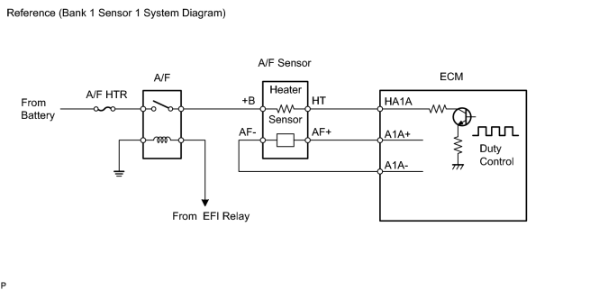
|
DTC No. |
DTC Detection Condition |
Trouble Area |
|---|---|---|
|
P0031 P0051 |
Air Fuel Ratio (A/F) sensor heater current less than 0.8 A (1 trip detection logic) |
|
|
P0032 P0052 |
Air Fuel Ratio (A/F) sensor heater current more than 10 A (1 trip detection logic) |
|
HINT:
- Bank 1 refers to the bank that includes No. 1 cylinder.
- Bank 2 refers to the bank that does not include No. 1 cylinder.
- Sensor 1 refers to the sensor closest to the engine assembly.
- Sensor 2 refers to the sensor farthest away from the engine assembly.
MONITOR DESCRIPTION
The ECM uses information from the Air Fuel Ratio (A/F) sensor to regulate the air fuel ratio and keep it close to the stoichiometric level. This maximizes the ability of the Three-Way Catalytic Converter (TWC) to purify the exhaust gases.
The A/F sensor detects oxygen levels in the exhaust gas and transmits the information to the ECM. The inner surface of the sensor element is exposed to the outside air. The outer surface of the sensor element is exposed to the exhaust gas. The sensor element is made of platinum coated zirconia and includes an integrated heating element.
The zirconia element generates a small voltage when there is a large difference in the oxygen concentrations between the exhaust gas and outside air. The platinum coating amplifies this voltage generation.
The A/F sensor is more efficient when heated. When the exhaust gas temperature is low, the sensor cannot generate useful voltage signals without supplementary heating. The ECM regulates the supplementary heating using a duty-cycle approach to adjust the average current in the sensor heater element. If the heater current is outside the normal range, the signal transmitted by the A/F sensor will be inaccurate. As a result, the ECM will be unable to regulate air fuel ratio properly.
When the current in the A/F sensor heater is outside the normal operating range, the ECM interprets this as a malfunction in the sensor heater and sets a DTC.
Example:
The ECM sets DTC P0032 or P0052 when the current in the A/F sensor heater is more than 10 A. Conversely, when the heater current is less than 0.8 A, DTC P0031 or P0051 is set.
MONITOR STRATEGY
|
Related DTCs |
P0031: A/F sensor heater (bank 1) range check (low current) P0032: A/F sensor heater (bank 1) range check (high current) P0051: A/F sensor heater (bank 2) range check (low current) P0052: A/F sensor heater (bank 2) range check (high current) |
|
Required sensors / components |
A/F sensor heater (bank 1 and 2) |
|
Required sensors / components |
- |
|
Frequency of operation |
Continuous |
|
Duration |
10 seconds |
|
MIL operation |
Immediate |
|
Sequence of operation |
None |
TYPICAL ENABLING CONDITIONS
All:
|
Monitor runs whenever following DTCs not present |
P0300 - P0308 (misfire) |
P0031 and P0051 (Low current):
|
Battery voltage |
10.5 V or more |
|
A/F sensor heater duty ratio |
50% or more |
|
Time after engine start |
10 seconds or more |
P0032 and P0052 (High current):
|
Time after engine start |
10 seconds or more |
TYPICAL MALFUNCTION THRESHOLDS
P0031 and P0051:
|
A/F sensor heater current |
Less than 0.8 A |
P0032 and P0052:
|
A/F sensor heater current |
More than 10 A |
COMPONENT OPERATING RANGE
P0031 and P0051:
|
A/F sensor heater current |
1.8 to 3.4 A at 20°C (68°F) |
WIRING DIAGRAM
Refer to DTC P2195
.
INSPECTION PROCEDURE
HINT:
Read freeze frame data using the intelligent tester. Freeze frame data records the engine conditions when malfunctions are detected. When troubleshooting, freeze frame data can help determine if the vehicle was running or stopped, if the engine was warmed up or not, if the air fuel ratio was lean or rich, and other data from the time the malfunction occurred.
PROCEDURE
|
1. |
INSPECT AIR FUEL RATIO SENSOR (HEATER RESISTANCE) |
|
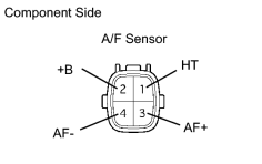
(a) Disconnect the A53 or A54 Air Fuel Ratio (A/F) sensor connector. (b) Measure the resistance of the A/F sensor connector. Standard resistance:
(c) Reconnect the A/F sensor connector. |
|
| NG |

|
|

|
2. |
INSPECT A/F RELAY (Marking: A/F HTR) |
|
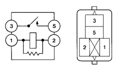
(a) Remove the A/F relay from the No. 8 engine room relay block. (b) Measure the resistance of the A/F relay. Standard resistance:
(c) Reinstall the A/F relay. |
|
| NG |
|
|
|
3. |
INSPECT ECM (HA1A OR HA2A VOLTAGE) |
|
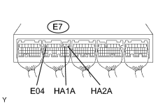
(a) Turn the ignition switch ON. (b) Measure the voltage of the E7 ECM connector. Standard voltage:
HINT:
|
|
| OK |
|
|
|
4. |
CHECK HARNESS AND CONNECTOR (A/F SENSOR - ECM, A/F SENSOR - A/F RELAY) |
(a)
Check harness and connector
.
| NG |
|
| OK |
|

|

|