- Open or short in Air Fuel Ratio (A/F) sensor (sensor 1) circuit
- Air Fuel Ratio (A/F) sensor (sensor 1)
- ECM
| Last Modified: 4-30-2014 | 6.6 C | Doc ID: RM000000WC200IX |
| Model Year: 2006 | Model: LX470 | Prod Date Range: [05/2005 - ] |
| Title: 2UZ-FE ENGINE CONTROL SYSTEM: SFI SYSTEM: P2A00,P2A03; A/F Sensor Circuit Slow Response (Bank 1 Sensor 1); 2006 MY LX470 [05/2005 - ] | ||
|
DTC |
P2A00 |
A/F Sensor Circuit Slow Response (Bank 1 Sensor 1) |
|
DTC |
P2A03 |
A/F Sensor Circuit Slow Response (Bank 2 Sensor 1) |
DESCRIPTION
- DTC P2A00 indicates malfunctions related to the bank 1 A/F sensor.
- DTC P2A03 indicates malfunctions related to the bank 2 A/F sensor.
- Bank 1 refers to the bank that includes No. 1 cylinder.
- Bank 2 refers to the bank that includes No. 2 cylinder.
- Sensor 1 refers to the sensor mounted in front of the Three-Way Catalytic Converter (TWC) and is located near the engine assembly.
Refer to DTC P2195 (
![2006 MY LX470 [05/2005 - ]; 2UZ-FE ENGINE CONTROL SYSTEM: SFI SYSTEM: P2195-P2198; Oxygen (A/F) Sensor Signal Stuck Lean (Bank 1 Sensor 1)+](../../../../stylegraphics/info.gif "2006 MY LX470 [05/2005 - ]; 2UZ-FE ENGINE CONTROL SYSTEM: SFI SYSTEM: P2195-P2198; Oxygen (A/F) Sensor Signal Stuck Lean (Bank 1 Sensor 1)+") ).
).
|
DTC No. |
DTC Detection Condition |
Trouble Area |
|---|---|---|
|
P2A00 P2A03 |
Calculated test value for Air Fuel Ratio (A/F) sensor response rate deterioration level is less than threshold. |
|
MONITOR DESCRIPTION
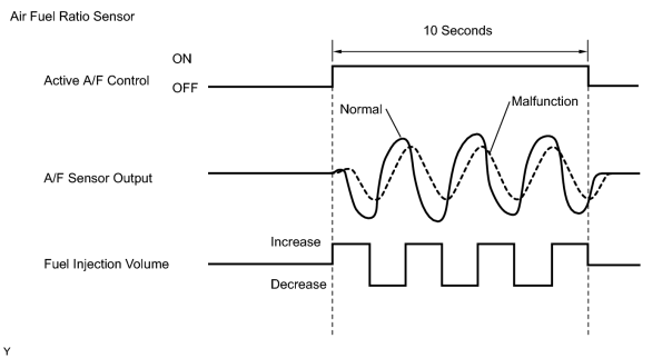
After engine is warmed up, the ECM performs air fuel ratio feedback control to regulate the air fuel ratio at stoichiometric ratio. In addition, this vehicle performs Active Air Fuel Ratio (A/F) Control for approximately 10 seconds after preconditions are met in order to measure the A/F sensor response rate. During active air fuel ratio control, the ECM forcibly increases and decreases the injection volume a certain amount based on learned stoichiometric air fuel ratio during usual air fuel feedback control, and measures the A/F sensor response rate. The ECM receives a signal from the A/F sensor while performing active A/F control and uses it to calculate the A/F sensor response rate deterioration level.
If the test value for A/F sensor response rate deterioration level is less than the threshold, ECM interprets this as a malfunction, and sets the DTC.
MONITOR STRATEGY
|
Related DTCs |
P2A00: Air fuel ratio (A/F) sensor (bank 1) slow response P2A03: Air fuel ratio (A/F) sensor (bank 2) slow response |
|
Required Sensors/Components (Main) |
A/F sensor |
|
Frequency of Operation |
Once per driving cycle |
|
Duration |
10 to 15 seconds |
|
MIL Operation |
2 driving cycles |
|
Sequence of Operation |
None |
TYPICAL ENABLING CONDITIONS
|
Monitor runs whenever following DTCs not present |
P0031, P0032, P0051, P0052 (A/F sensor heater - Sensor 1) P0100 - P0103 (MAF meter) P0110 - P0113 (IAT sensor) P0115 - P0118 (ECT sensor) P0120 - P0223, P2135 (TP sensor) P0125 (Insufficient ECT for Closed Loop) P0171, P0172 (Fuel system) P0300 - P0308 (Misfire) P0335 (CKP sensor) P0340, P0341 (CMP sensor) P0442 - P0456 (EVAP system) P0500 (VSS) P2196, P2198 (A/F sensor - rationality) P2440 (A/R control valve stuck open) P2441 (A/R control valve stuck close) P2444 (AIP stuck ON) P2445 (AIP stuck OFF) |
|
Active A/F control |
Performing |
|
Active A/F control is performed when the following conditions set |
- |
|
Battery Voltage |
11 V or more |
|
ECT |
75°C (167°F) or more |
|
Idle |
OFF |
|
Engine RPM |
Less than 4,000 rpm |
|
A/F sensor status |
Activated |
|
Fuel cut |
OFF |
|
Engine load |
10 to 70% |
|
Shift position |
2nd or more |
|
Catalyst monitor |
Not executing |
|
Intake air amount |
2.5 to 12 g/sec. |
TYPICAL MALFUNCTION THRESHOLDS
|
Response rate deterioration level |
Less than 0.2 V |
MONITOR RESULT
Detailed information on Checking Monitor Status
.
The test value and test limit information are described as shown in the following table. Check the monitor result and test values after performing the monitor drive pattern (refer to "Confirmation Monitor").
- Monitor Identification Data (MID) is assigned to each emission-related component.
- TID Identification (TID) is assigned to each test value.
- Scaling is used to calculate the test value indicated on generic OBD II scan tools.
Air fuel ratio sensor bank 1 sensor 1
|
MID |
TID |
Scaling |
Description of Test Value |
Minimum Test Limit |
Maximum Test Limit |
|---|---|---|---|---|---|
|
$01 |
$8E |
Multiply by 0.0003 (No dimension) |
Response rate deterioration level for A/F sensor |
Malfunction criterion |
FF |
Air fuel ratio sensor bank 2 sensor 1
|
MID |
TID |
Scaling |
Description of Test Value |
Minimum Test Limit |
Maximum Test Limit |
|---|---|---|---|---|---|
|
$05 |
$8E |
Multiply by 0.0003 (No dimension) |
Response rate deterioration level for A/F sensor |
Malfunction criterion |
FF |
CONFIRMATION DRIVING PATTERN
HINT:
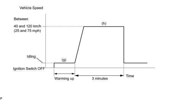
Performing this confirmation pattern will activate the air fuel ratio (A/F) sensor response monitor.
(a) Connect the intelligent tester to the CAN VIM. Then connect the CAN VIM to the DLC3.
(b) Turn the ignition switch ON.
(c) Turn the tester ON.
(d) Clear DTCs (if set)
.
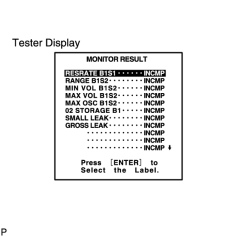
(e) Enter the following menus: DIAGNOSIS / ENHANCED OBD II / MONITOR INFO / MONITOR RESULT.
(f) Check that RES RATE B1 S1 is INCOMPL.
(g) Start the engine and warm it up.
(h) Drive the vehicle at between 40 km/h and 120 km/h (25 mph and 75 mph) for 3 minutes. However, the vehicle should be driven at a constant speed.
(i) Check the monitor result values on the intelligent tester by entering the following menus: DIAGNOSIS / ENHANCED OBD II / MONITOR INFO / TEST RESULT.
(j) If the values indicated on the tester do not change, perform READINESS MONITOR DRIVE PATTERN for the A/F sensor and the heated oxygen sensor
.
HINT:
Completion of all A/F sensor monitors are required to change the value in TEST RESULT.
(k) Note the value of the Monitor Result.
(l) Enter the following menus: DIAGNOSIS / ENHANCED OBD II / DTC INO / PENDING CODES.
(m) Check if any pending DTCs are set.
WIRING DIAGRAM
Refer to DTC P2195
.
INSPECTION PROCEDURE
HINT:
Intelligent tester only:
Malfunctioning areas can be identified by performing the A/F CONTROL function provided in the ACTIVE TEST. The A/F CONTROL function can help to determine whether the Air Fuel Ratio (A/F) sensor, Heated Oxygen (HO2) sensor and other potential trouble areas are malfunctioning.
The following instructions describe how to conduct the A/F CONTROL operation using the intelligent tester.
- Connect the intelligent tester to the CAN VIM. Then connect the CAN VIM to the DLC3.
- Start the engine and turn the tester ON.
- Warm up the engine at an engine speed of 2,500 rpm for approximately 90 seconds.
- On the intelligent tester, enter the following menus: DIAGNOSIS / ENHANCED OBD II / ACTIVE TEST / A/F CONTROL.
- Perform the A/F CONTROL operation with the engine in an idling condition (press the RIGHT or LEFT button to change the fuel injection volume).
- Monitor the output voltages of the A/F and HO2 sensors (AFS B1S1 (AFS B2S1) and O2S B1S2 (O2S B2S2)) displayed on the tester.
HINT:
- The A/F CONTROL operation lowers the fuel injection volume by 12.5% or increases the injection volume by 25%.
- Each sensor reacts in accordance with increases and decreases in the fuel injection volume.
Standard:
|
Tester Display (Sensor) |
Injection Volume |
Status |
Voltage |
|---|---|---|---|
|
AFS B1S1 (AFS B2S1) (A/F) |
+25% |
Rich |
Less than 3.0 |
|
AFS B1S1 (AFS B2S1) (A/F) |
-12.5% |
Lean |
More than 3.35 |
|
O2S B1S2 ( O2S B2S2) (HO2) |
+25% |
Rich |
More than 0.55 |
|
O2S B1S2 (O2S B2S2) (HO2) |
-12.5% |
Lean |
Less than 0.4 |
NOTICE:
The Air Fuel Ratio (A/F) sensor has an output delay of a few seconds and the Heated Oxygen (HO2) sensor has a maximum output delay of approximately 20 seconds.
|
Case |
A/F Sensor (Sensor 1) Output Voltage |
HO2 Sensor (Sensor 2) Output Voltage |
Main Suspected Trouble Area |
||
|---|---|---|---|---|---|
|
1 |
Injection Volume +25% -12.5% |

|
Injection Volume +25% -12.5% |
|
- |
|
Output Voltage More than 3.35 V Less than 3.0 V |

|
Output Voltage More than 0.55 V Less than 0.4 V |

|
||
|
2 |
Injection Volume +25% -12.5% |
|
Injection Volume +25% -12.5% |
|
|
|
Output Voltage Almost no reaction |
|
Output Voltage More than 0.55 V Less than 0.4 V |
|
||
|
3 |
Injection Volume +25% -12.5% |
|
Injection Volume +25% -12.5% |
|
|
|
Output Voltage More than 3.35 V Less than 3.0 V |
|
Output Voltage Almost no reaction |
|
||
|
4 |
Injection volume +25% -12.5% |
|
Injection Volume +25% -12.5% |
|
|
|
Output Voltage Almost no reaction |
|
Output Voltage Almost no reaction |
|
||
- Following the A/F CONTROL procedure enables technicians to check and graph the voltage outputs of both the A/F and HO2 sensors.
- To display the graph, enter the following menus: DIAGNOSIS / ENHANCED OBD II / ACTIVE TEST / A/F CONTROL / USER DATA / AFS B1S1 and O2S B1S2 or AFS B2S1 and O2S B2S2. Then press the YES button and ENTER button, followed by the F4 button.
HINT:
- DTC P2A00 may be also set when the air fuel ratio is stuck rich or lean.
- A low A/F sensor voltage could be caused by a rich air fuel mixture. Check for conditions that would cause the engine to run rich.
- A high A/F sensor voltage could be caused by a lean air fuel mixture. Check for conditions that would cause the engine to run lean.
- Read freeze frame data using the intelligent tester. Freeze frame data records the engine conditions when malfunctions are detected. When troubleshooting, freeze frame data can help determine if the vehicle was running or stopped, if the engine was warmed up or not, if the air fuel ratio was lean or rich, and other data from the time the malfunction occurred.
PROCEDURE
|
1. |
CHECK ANY OTHER DTCS OUTPUT (IN ADDITION TO DTC P2A00 AND/OR P2A03) |
(a) Connect the intelligent tester to the CAN VIM. Then connect the CAN VIM to the DLC3.
(b) Turn the ignition switch ON and turn the tester ON.
(c) Enter the following menus: DIAGNOSIS / ENHANCED OBD II / DTC INFO / CURRENT CODES.
(d) Read DTCs.
Result:
|
Display (DTC Output) |
Proceed to |
|---|---|
|
P2A00 and/or P2A03 |
A |
|
P2A00 and/or P2A03 and other DTCs |
B |
HINT:
If any DTCs other than P2A00 and/or P2A03 are output, troubleshoot those DTCs first.
| B |

|
|

|
2. |
INSPECT AIR FUEL RATIO SENSOR (HEATER RESISTANCE) |
|
(a) Disconnect the A53 or A54 Air Fuel Ratio (A/F) sensor connector. (b) Measure the resistance of the A/F sensor connector. Standard resistance:
(c) Reconnect the A/F sensor connector. |

|
| NG |
|
|
|
3. |
CHECK HARNESS AND CONNECTOR |
(a)
Check harness and connector
.
| NG |
|
|
|
4. |
PERFORM CONFIRMATION DRIVING PATTERN |
|
|
5. |
CHECK WHETHER DTC OUTPUT RECURS (DTC P2A00 AND/OR P2A03) |
(a) Read DTCs using the intelligent tester.
(b) Enter the following menus: DIAGNOSIS / ENHANCED OBD II / DTC INFO / PENDING CODES.
Result:
|
Display (DTC Output) |
Proceed to |
|---|---|
|
P2A00 and/or P2A03 |
A |
|
No output |
B |
| B |
|
|
|
6. |
REPLACE AIR FUEL RATIO SENSOR |
(a)
Replace A/F sensor
.
|
|
7. |
PERFORM CONFIRMATION DRIVING PATTERN |
|
|
8. |
CHECK WHETHER DTC OUTPUT RECURS (DTC P2A00 AND/OR P2A03) |
(a) Read DTCs using the intelligent tester.
(b) Enter the following menus: DIAGNOSIS / ENHANCED OBD II / DTC INFO / PENDING CODES.
Result:
|
Display (DTC Output) |
Proceed to |
|---|---|
|
P2A00 and/or P2A03 |
A |
|
No output |
B |
| A |
|
CHECK EXTREMELY RICH OR LEAN ACTUAL AIR FUEL RATIO (REFER TO DTC P0171 PROCEDURE) |
| B |
|

|

|