- CAN main bus line or connector
| Last Modified: 4-30-2014 | 6.6 J | Doc ID: RM000000WIM004X |
| Model Year: 2006 | Model: LX470 | Prod Date Range: [05/2005 - ] |
| Title: CAN COMMUNICATION: CAN COMMUNICATION SYSTEM: Open in CAN Main Bus Line; 2006 MY LX470 [05/2005 - ] | ||
|
Open in CAN Main Bus Line |
DESCRIPTION
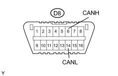
There may be an open circuit in the CAN main bus line and/or the DLC3 sub bus line when the resistance between terminals 6 (CANH) and 14 (CANL) of the DLC3 is 67 Ω or higher.
|
Symptom |
Trouble Area |
|---|---|
|
Resistance between terminals 6 (CANH) and 14 (CANL) of DLC3 is 67 Ω or more. |
|
WIRING DIAGRAM
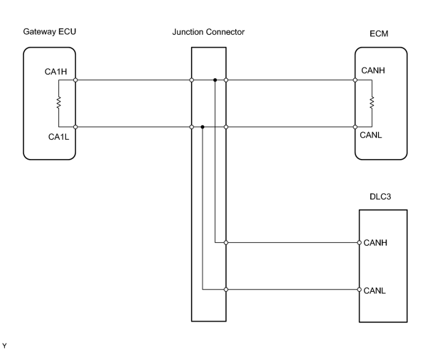
INSPECTION PROCEDURE
PROCEDURE
|
1. |
CHECK DLC3 |
|
(a) Measure the resistance of the DLC3. Standard resistance:
NOTICE:
When the measured value is 132 Ω or higher and a CAN communication system diagnostic trouble code is output, there may be a fault besides disconnection of the DLC3 sub bus line. For that reason, troubleshooting should be performed again from "HOW TO PROCEED WITH TROUBLESHOOTING"
|
|
![2006 MY LX470 [05/2005 - ]; CAN COMMUNICATION: CAN COMMUNICATION SYSTEM: HOW TO PROCEED WITH TROUBLESHOOTING](../../../../stylegraphics/info.gif "2006 MY LX470 [05/2005 - ]; CAN COMMUNICATION: CAN COMMUNICATION SYSTEM: HOW TO PROCEED WITH TROUBLESHOOTING")
| B |

|
REPAIR OR REPLACE DLC3 SUB BUS LINE OR CONNECTOR (CANH, CANL) |
|

|
2. |
CHECK CAN MAIN BUS LINE FOR DISCONNECTION (FOR ECM) |
|
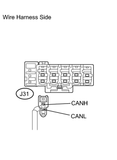
(a) Disconnect the J31 ECM main bus line connector from the junction connector B side. NOTICE:
(b) Measure the resistance of the wire harness side connector. Standard resistance:
|
|
| NG |
|
|
|
3. |
CONNECT CONNECTOR |
(a) Reconnect the J31 ECM main bus line connector to the junction connector B side.
|
|
4. |
CHECK CAN MAIN BUS LINE FOR DISCONNECTION (FOR GATEWAY ECU) |
|
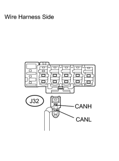
(a) Disconnect the J32 gateway ECU main bus line connector from the junction connector B side. NOTICE:
(b) Measure the resistance of the wire harness side connector. Standard resistance:
|
|
| NG |
|
| OK |
|
|
5. |
CONNECT CONNECTOR |
Reconnect the J32 ECM main bus line connector to the junction connector B side.
|
|
6. |
CHECK ECM |
|
(a) Disconnect the E9 ECM connector. (b) Measure the resistance of the ECM connector. Standard resistance:
|
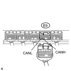
|
| NG |
|
| OK |
|
|
7. |
CONNECT CONNECTOR |
(a) Reconnect the J32 gateway ECU main bus line connector to the junction connector B side.
|
|
8. |
CHECK GATEWAY ECU |
|
(a) Disconnect the G5 gateway ECU connector. (b) Measure the resistance of the gateway ECU connector. Standard resistance:
|
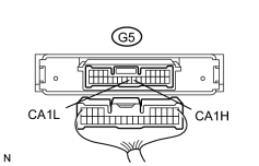
|
| NG |
|
| OK |
|

|

|